Vibrating device, jet flow generating device, electronic device, and manufacturing method of vibrating device

a jet flow generating device and vibrating device technology, applied in the direction of mechanical vibration separation, electrical apparatus casing/cabinet/drawer, instruments, etc., can solve the problems of excessive noise and inability to effectively vibrate the gas, and achieve the effect of effective vibration and efficient vibration

Inactive Publication Date: 2009-04-02
SONY CORP
View PDF3 Cites 33 Cited by
  • Summary
  • Abstract
  • Description
  • Claims
  • Application Information

AI Technical Summary

Benefits of technology

[0099]Thus, according to the present invention, efficient vibrations can be generated at the vibrating member, thereby effectively applying vibrations to the gas.

Problems solved by technology

On the other hand, while the amount of gas blown by the device can be increased by increasing the amplitude of the vibrating plate, this not only generates flexing of the vibrating plate such that the gas cannot be effectively vibrated, but also can be the source of excessive noise.

Method used


Image

  • Vibrating device, jet flow generating device, electronic device, and manufacturing method of vibrating device
  • Vibrating device, jet flow generating device, electronic device, and manufacturing method of vibrating device
  • Vibrating device, jet flow generating device, electronic device, and manufacturing method of vibrating device

Examples


Embodiment Construction

[0209]The following is a description of embodiments of the present invention, with reference to the drawings.

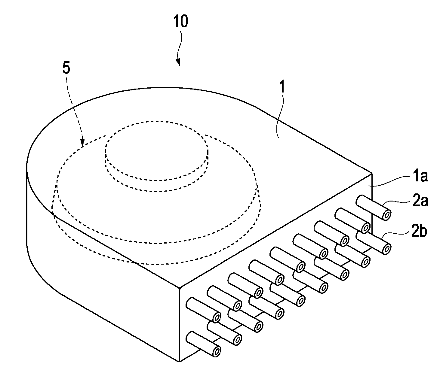
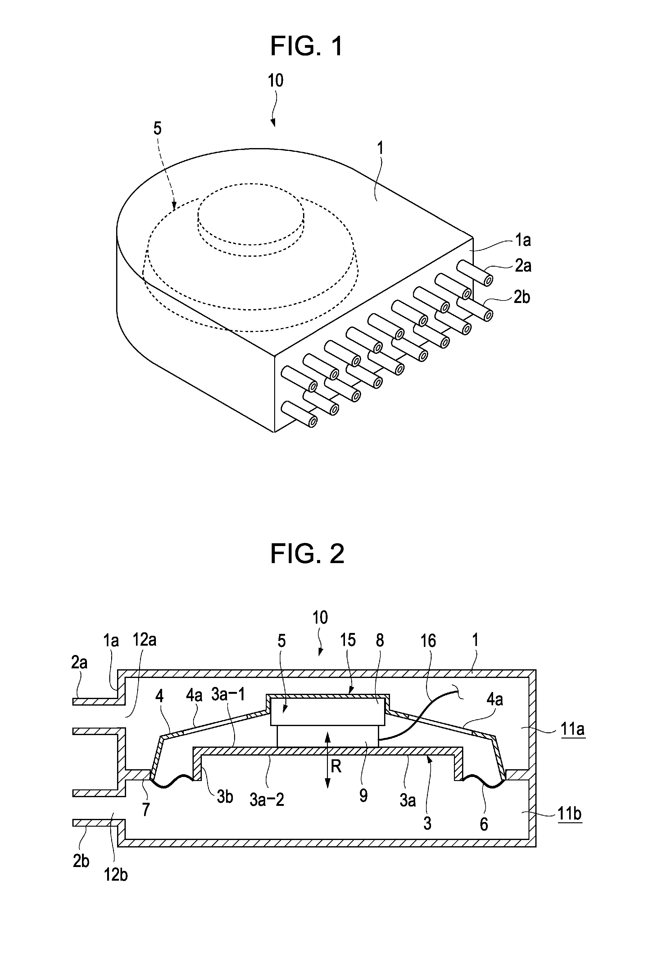
[0210]FIG. 1 is a perspective view illustrating a jet flow generating device according to an embodiment of the present invention, and FIG. 2 is a cross-sectional view of the jet flow generating device shown in FIG. 1.

[0211]A jet flow generating device 10 has a housing 1 of which the rear portion has a cylindrical shape, and a vibrating device disposed within the housing 1. Multiple nozzles 2a and 2b are each arrayed on a front face 1a of the housing 1. As shown in FIG. 2, the interior of the housing is divided into an upper chamber 11a and lower chamber 11b by a vibrating device 15, an attaching portion 7 whereby the vibrating device 15 is attached. Openings 12a and 12b are formed at positions corresponding to nozzles 2a and 2b, on the front face 1a of the housing 1 where the nozzles 2a and 2b are situated. Thus, the upper chamber 11a and the lower chamber 11b each communicat...


PUM

PropertyMeasurementUnit
residual magnetic flux densityaaaaaaaaaa
thicknessaaaaaaaaaa
magnetic flux densityaaaaaaaaaa

Abstract

Provided is a vibrating device which can generate efficient vibrations in a vibrating member and efficiently apply vibrations to a gas, a jet flow generating device in which the vibrating device has been implemented, and an electronic device in which the jet flow generating device has been implemented. A jet flow generating device 10 has a vibrating device 15 including a frame 4, and actuator 5 mounted on the frame 4, and a vibrating member 3 supported on the frame 4 by an elastic supporting member 6. The vibrating member 3 has a side plate 3b formed on the perimeter portion of a disc-shaped vibrating plate 3a, for example. Vibration of the vibrating member 3 applies vibrations to air within chambers 11a and 11b, whereby gas can alternatingly be blown from nozzles 2a and 2b.

Description

TECHNICAL FIELD[0001]The present invention relates to a vibrating device for causing vibrations in a jet flow of gas, a jet flow generating device in which the vibrating device is implemented, an electronic device in which the jet flow generating device is implemented, and a method for manufacturing the vibrating device.BACKGROUND ART[0002]There has been known a problem relating to increase in the amount of heat generated from heat sources in PCs (personal computers) such as ICs (Integrated Circuit), owing to the increase in performance of PCs. A known method for dissipating the heat involves bringing the IC in contact with radiating fins formed of a metal such as aluminum or the like, for example, so as to dissipate the heat from the IC by head conduction though the radiating fins. There is also a method known wherein a fan is used to forcibly displace warmed air within the PC housing and introduce the cooler ambient air, thereby dissipating heat. There is further a method known wh...

Claims


Application Information

Patent Timeline
Patent Type & Authority Applications(United States)
IPC IPC(8): H05K7/20F28F7/00B23P17/04F04B17/03F28F13/12
CPCF04F7/00G06F1/203H05K7/20172Y10T29/49002H01L2924/0002H01L2924/00B06B1/04
Inventor ISHIKAWA, HIROICHINAKAYAMA, NORIKAZUMAKINO, TAKUYAMUKASA, TOMOHARURYOSON, HIROYUKI
Owner SONY CORP
Why Eureka
Try Eureka