In-Furnace Gas Injection Port

a gas injection port and furnace technology, applied in the direction of lighting and heating apparatus, combustion types, and lump and pulverizing fuel, can solve the problems of increased cost and weight, increased and ineffective prevention of ash adhesion or growth of clinker, etc., to achieve high reliability and fuel combustion. high, the effect of reducing nox and co combustion

Inactive Publication Date: 2009-04-02
BABCOCK HITACHI KK
View PDF10 Cites 10 Cited by
  • Summary
  • Abstract
  • Description
  • Claims
  • Application Information

AI Technical Summary

Benefits of technology

[0044]According to the invention described in claim 7, if the gas injection port is used as an AAP disposed on the furnace wall at the downstream portion of a two-s...

Problems solved by technology

According to conventional techniques, where the contracted flow of the gas injection flow is increased in effects, ash adhesion or growth of clinker is not effectively prevented particularly on a furnace throat wall of a burner port.
According to the description of P...

Method used


Image

  • In-Furnace Gas Injection Port
  • In-Furnace Gas Injection Port
  • In-Furnace Gas Injection Port

Examples


embodiment 1

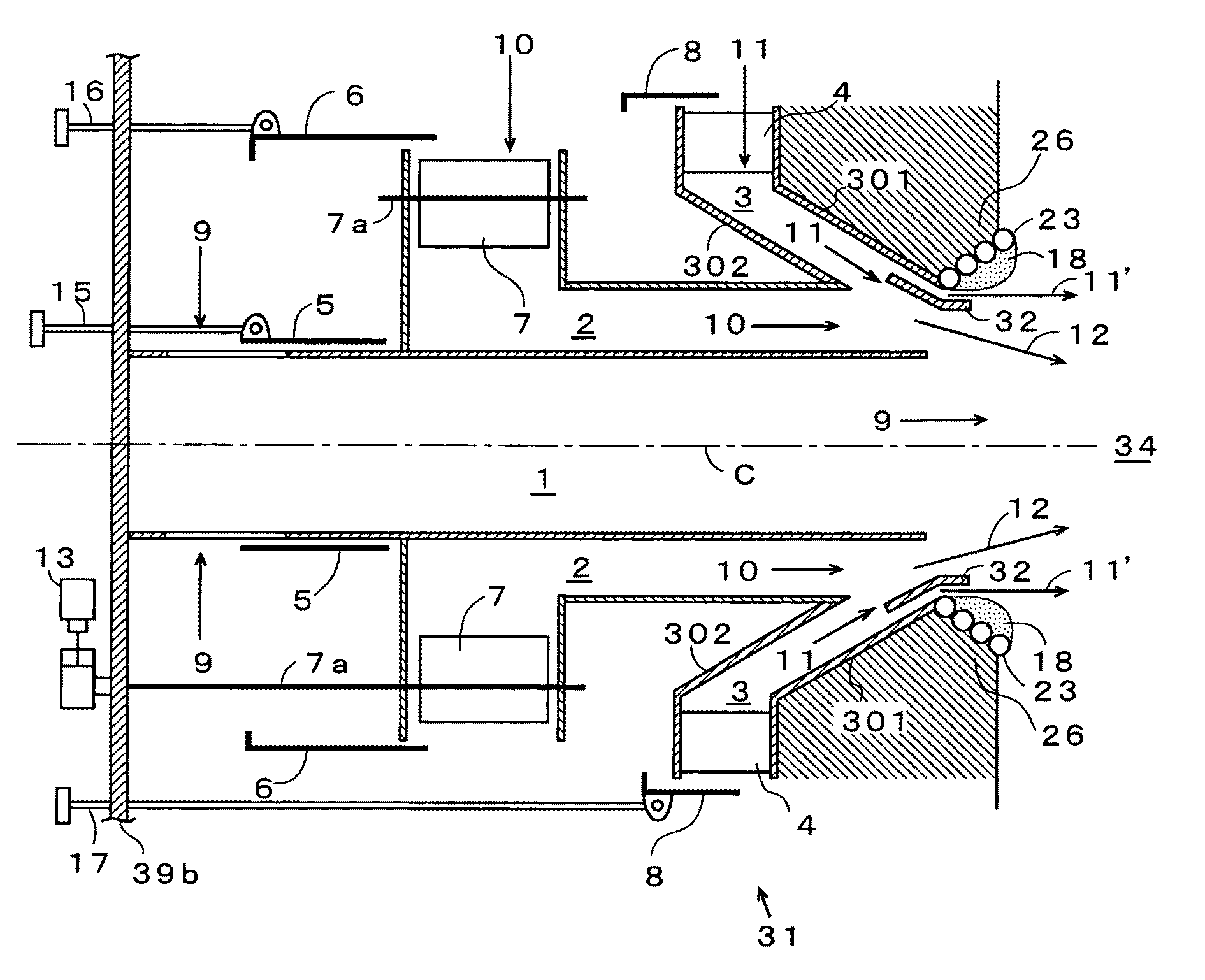
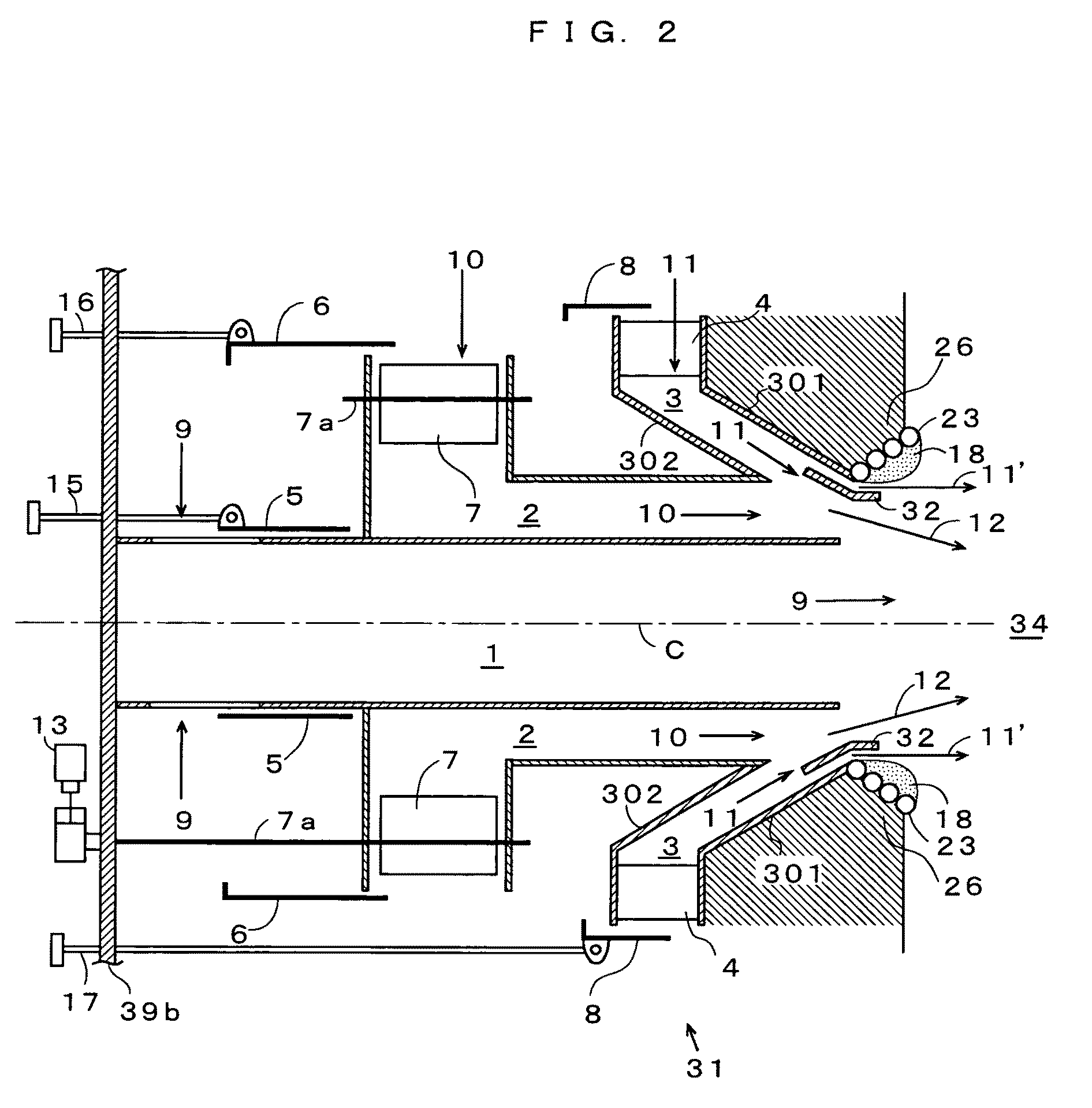
[0067]Next, an explanation will be made for aspects of the after airport (hereinafter referred to as “port” or “AAP”) 31 applied to the boiler furnace 34 by referring to the following embodiments.

[0068]FIG. 2 is a sectional view of the port 31 in the present embodiment (a sectional view taken along line A-A′ in FIG. 4). FIG. 3 is a perspective view in which the port 31 is partially omitted. FIG. 4 is a drawing of the port 31 which is viewed from the furnace 34 side.

[0069]The port 31 is arranged inside the window box 39b, and the air nozzle mechanism thereof is provided with a primary nozzle 1, a secondary nozzle 2 for injecting air of rotating flow along the outer circumference of the primary nozzle 1 as secondary air 10 and a tertiary nozzle 3 for injecting air of flow heading from the outside of the primary nozzle 1 to the central axis C of the port 31 as tertiary air 11.

[0070]The primary nozzle 1, the secondary nozzle 2 and the tertiary nozzle 3 are of a coaxial nozzle structure....

embodiment 2

[0086]FIG. 8 shows a sectional view of the port 31 of Embodiment 2. Additionally, FIG. 9 and FIG. 10 are schematic diagrams of the port 31, which is a comparative example for comparison with the port 31 of Embodiment 2 given in FIG. 8.

[0087]As the port shown in FIG. 8, the primary nozzle 1, the secondary nozzle 2 and the tertiary nozzle 3 are shown, through which the primary air, the secondary air and the tertiary air flow respectively in a concentric manner. At least such a structure is acceptable that a flow from the outer circumference of the tertiary nozzle 3 in the present embodiment toward the central axis C of the port is increased and allowed to flow through a port opening of the furnace 34 (throat wall 26), thereby the air injection flow is able to appropriately form a so-called contracted flow. In other words, the primary nozzle 1 and the secondary nozzle 2 are not essential in forming the so-called contracted flow.

[0088]Air flowing through the primary nozzle 1, which is a...

embodiment 3

[0110]FIG. 11 is a schematic diagram of the port 31 showing the present embodiment 3. In the constitution given in FIG. 11, the same parts as those of the constitution given in FIG. 8 are given the same numerals or symbols, an explanation of which will be omitted here.

[0111]In the present embodiment, a parallel portion 26a which is constant in cross section of the channel and parallel to the central axis C is provided on the throat wall 26 of enlarged pipe configuration of the port 31. Further, a cylindrical portion 32a running along the parallel portion 26a is also provided on the louver 32. Additionally, the contracted flow from the tertiary nozzle 3 partially flows into a space between the louver 32 and the throat wall 26 of enlarged pipe configuration, a flow 11′, or a part of the tertiary air 11 which seals the surface of the throat wall 26 of the furnace 34, flows effectively in the vicinity of the wall surface of the throat wall 26, thus making it possible to eliminate a nega...


PUM


Abstract

Tertiary nozzle of port for gas injection into furnace includes a contracted flow producing channel provided obliquely toward central axis from the upstream side of gas flow so that the gas flow has a velocity component heading from the outer circumferential side of the port toward the central axis and a velocity component heading along the central axis toward the interior of the furnace, and including louver disposed for guiding so that the gas flows along the surface of throat wall of enlarged pipe configuration wherein the gas channel is enlarged at a furnace wall opening disposed at an outlet area of the contracted flow producing channel. Accordingly, there can be provided a gas injection port that not depending on conditions, such as the flow rate of gas injected from the port, without inviting any complication of apparatus structuring or cost increase, enables preventing of the growth in lump form of clinker caused by ash adhesion and fusion on the wall surface of throat enlarged pipe portion of the furnace.

Description

TECHNICAL FIELD [0001]The present invention relates to a port for gas injection into a furnace such as a boiler, and in particular to a port for gas injection into a furnace such as a boiler advantageous in preventing ash adhesion to a furnace opening.BACKGROUND ART [0002]Various types of ports for injecting gas such as air and exhaust gas into a furnace are disposed on the wall of a furnace such as a boiler. They include, for example, a burner for injecting fuel and combustion air as a combustion apparatus and an after air port (AAP) (which is also referred to as an over firing air port (OFA)) for feeding two-stage combustion air. The gas injection port described in the present specification is not limited to an after air port but includes a port for feeding exhaust gas and a burner port for combusting fuel, as long as it is a port for injecting gas into a furnace. Further, a wall surface of an enlarged pipe configuration opened on a furnace on which the port is disposed is to be r...

Claims


Application Information

Patent Timeline
IPC IPC(8): F23D11/38F23D11/36
CPCF23C7/008F23C7/02F23L9/02F23C2201/101F23C99/00
Inventor OCHI, YUSUKEBABA, AKIRAKURAMASHI, KOUJIOKAZAKI, HIROFUMITANIGUCHI, MASAYUKI
Owner BABCOCK HITACHI KK
Why Eureka
Try Eureka