Vegetation trimmer having a blowing function

a technology of vegetation trimmer and air blowing function, which is applied in the field of vegetation trimmer also having a blowing function, can solve the problems of not being able to provide a string trimmer having both a step-down gear mechanism and a cutting device, and achieve the effect of maintaining the efficiency of the air blowing function, reducing the amount of air exiting the air outlet, and reducing the amount of air leaving the air outl

Active Publication Date: 2009-04-09
BLACK & DECKER INC
View PDF38 Cites 14 Cited by
  • Summary
  • Abstract
  • Description
  • Claims
  • Application Information

AI Technical Summary

Benefits of technology

[0010]Since it would be extremely difficult to mold the duct and the guard as a single component, the duct must instead be mounted to the guard either during manufacture or during subsequent assembly by an end-user. However, this has the disadvantage that it creates a joint between the duct and the guard, through which air blown by the fan may escape by leakage, thereby reducing the amount of air exiting the air outlet of the duct and thus the overall efficiency of the air-blowing function of the trimmer. Accordingly, it is desirable that the duct should comprise a liner moulded as a single component which is able to direct the air from the volute to the air outlet of the duct without leakage, thereby maintaining the efficiency of the air-blowing function.
[0011]The efficiency of the air-blowing function may be maximized by locating the air outlet of the duct on the edge of the guard at a level which is parallel to a cutting element of the cutting head and with the air outlet oriented parallel

Problems solved by technology

This creates the technical problem that any air blown by the fan would also move in an opposite direction to the cutting head, thus also tending to act in an opposite direction to momentum which has been imparted to vegetation cut by the cutting head and therefore failing to expel the cut vegetation away from the cutting head as desired.
As a result, until now, it has been impossible to provide a string trimmer having both a step-down gear mechanism for more effective cutting of vegetation on the one ha

Method used


Image

  • Vegetation trimmer having a blowing function
  • Vegetation trimmer having a blowing function
  • Vegetation trimmer having a blowing function

Examples


Embodiment Construction

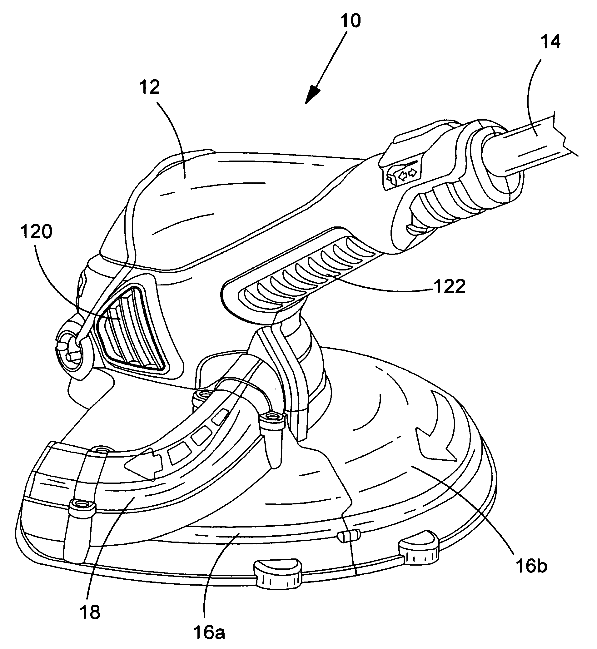
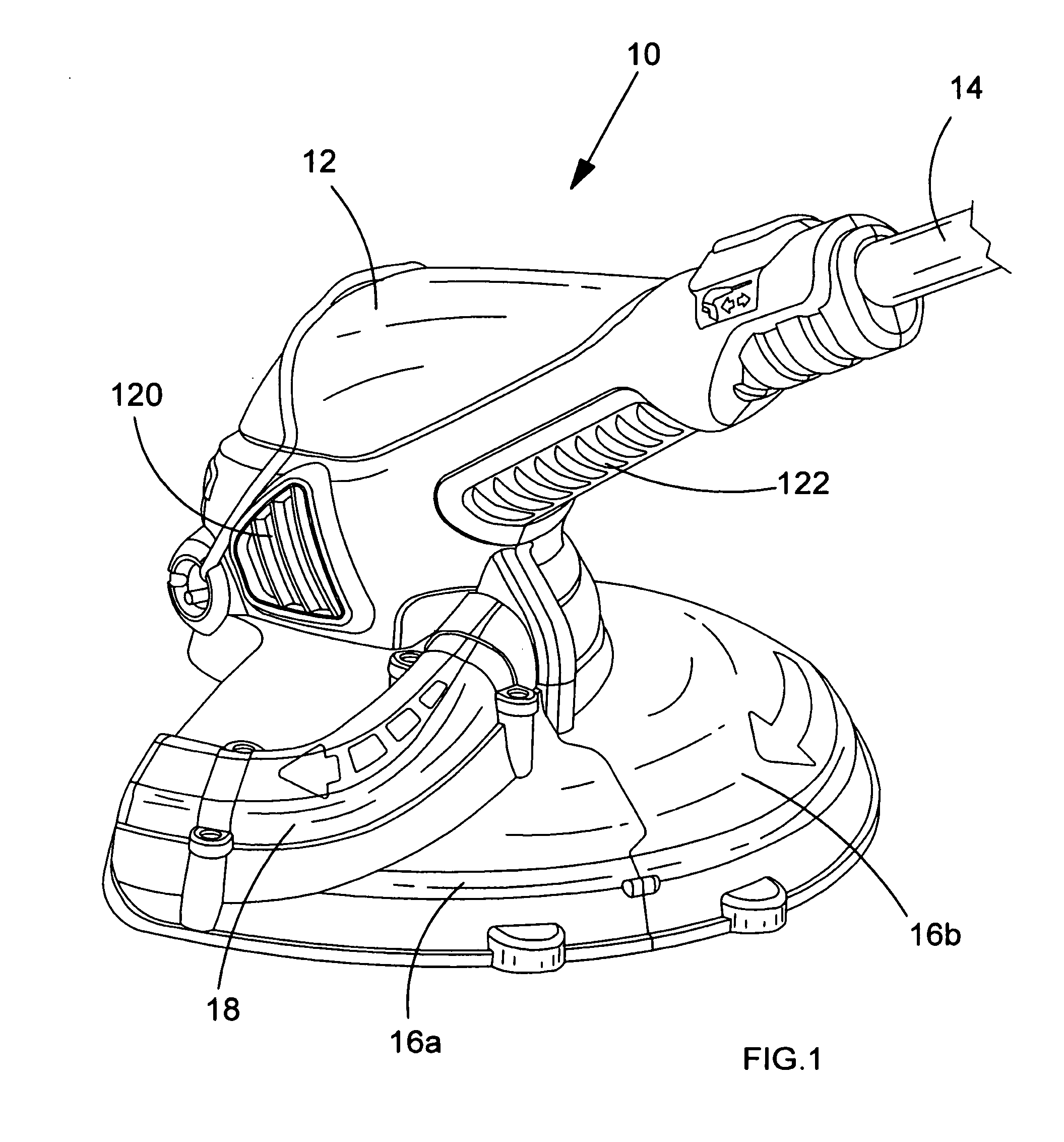
[0021]Referring firstly to FIG. 1, there is shown a lower end part of a vegetation trimmer 10, comprising a motor housing 12, a shaft 14 and a guard. The guard is formed from two component pieces 16a, 16b. Mounted on one of the component pieces 16a of the guard is a duct 18 for conveying air. The motor housing 12 additionally comprises air inlet vents 120 and outlet vents 122 for providing cooling air to a motor contained therein.

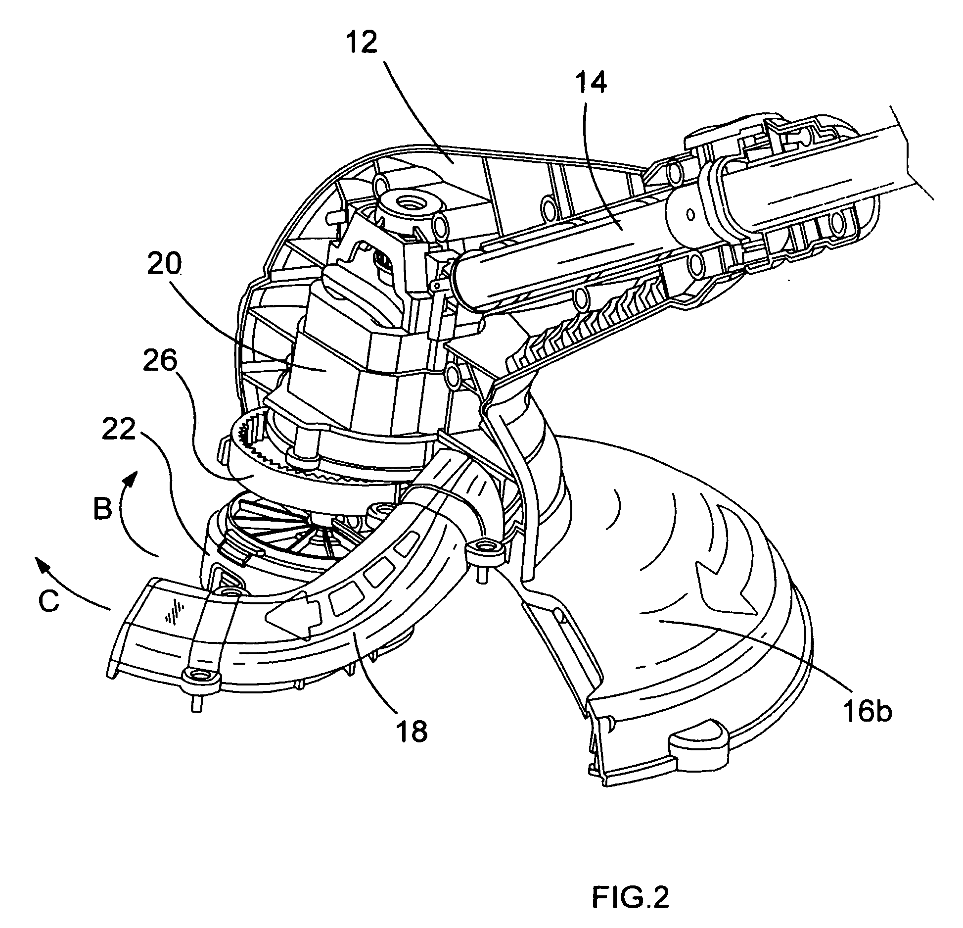
[0022]FIG. 2 is a partial cut-away view of the lower end part of the vegetation trimmer shown in FIG. 1. Within motor housing 12 there may be seen the motor 20. Electrical power for the motor is supplied thereto by electrical wires contained within shaft 14. When the motor is running, cutting head 22 is caused to rotate thereby in the direction indicated by arrow B. At the same time, air is expelled from duct 18 in the direction indicated by arrow C as a result of being blown by a fan contained within volute 24. As can be seen in FIG. 2, the drive train fro...


PUM


Abstract

The present invention provides a vegetation trimmer (10) comprising: a motor (20) having a motor output shaft (30); a cutting head (22) for cutting vegetation presented thereto; a gear mechanism (26, 34, 36, 38) for transmitting power from said motor output shaft (30) to said cutting head (22), the gear mechanism having a step-down gear ratio for reducing the rate of rotation of said cutting head (22) relative to the rate of rotation of said motor (20), said gear mechanism comprising a pinion wheel (34) mounted on the motor output shaft (30); and a fan (28) also mounted on the motor output shaft (30); wherein the gear mechanism (26, 34, 36, 38) further comprises an internal gear wheel (26) engaging with the pinion wheel (34) and connected to the cutting head (22), whereby the cutting head (22) rotates in the same direction (B) as the fan does (D) during operation of the motor (20).

Description

FIELD OF THE INVENTION[0001]The present invention concerns a vegetation trimmer also having a blowing function. Vegetation trimmers are well known power tools comprising a cutting head suitable for use in cutting vegetation, such as grass. The cutting head typically comprises one or more rotating blades, in which case the trimmer is generally known as a brush cutter, or one or more rotating lines, in which case it is generally known as a string trimmer, or a combination of both one or more blades and cutting lines.[0002]Vegetation trimmers which also have a blowing function are known as well. In such a case, air is directed by a fan either to expel vegetation which has already been cut by the trimmer from around the cutting head or to collect the cut vegetation into a receptacle. An example of such a vegetation trimmer which has a combination of blades and cutting line and which also has a blowing function is described in U.S. Pat. Nos. 6,442,845 and 6,460,253 also in the name of th...

Claims


Application Information

Patent Timeline
IPC IPC(8): A01D69/00
CPCA01D34/90A01D34/416
Inventor MILLION, PHILIP S.STONES, KEVIN
Owner BLACK & DECKER INC
Why Eureka
Try Eureka