Master Cylinder

a master cylinder and cylinder body technology, applied in the direction of rotary clutches, braking systems, fluid couplings, etc., can solve the problems of deteriorating area supply performance, affecting the operation of the master cylinder, so as to shorten the dead stroke, reduce the diameter of the radial hole, and improve the operation efficiency

Inactive Publication Date: 2009-04-09
BOSCH CORP
View PDF4 Cites 14 Cited by
  • Summary
  • Abstract
  • Description
  • Claims
  • Application Information

AI Technical Summary

Benefits of technology

[0016]It is an object of the present invention to provide a master cylinder which ensures brake fluid supply performance and self-support performance, allows simplification of piston processing, ensures sufficient piston strength, improves piston guide performance, and allows the piston to be assembled more easily by reducing the number of parts.
[0020]According to the master cylinder of the invention as structured above, the fluid passage connecting the hydraulic pressure chamber and the reservoir is formed by the predetermined number of axial grooves and the predetermined number of radial holes formed on the outer peripheral surface of the front end of the piston. Therefore, a passage area for brake fluid can be set large enough when the master cylinder is in the inoperative state. Consequently, the fluid supply performance and the fluid self-support performance of the master cylinder can be well ensured, and brake operations by a pump, other than those related to the operation of the master cylinder, can be reliably carried out.
[0021]Moreover, since the passage area for brake fluid can be set large enough by the axial grooves and the radial holes, the diameters of the radial holes can be reduced, thereby enabling shortening of the dead stroke by a corresponding amount.
[0022]Furthermore, the axial grooves and the radial holes are respectively formed at the front end of the piston, but since the passage area for brake fluid can be ensured to a reasonable extent by the axial grooves, the passage area for brake fluid ensured by the radial holes can be reduced. Accordingly, the number of the radial holes can be smaller than that of the axial grooves, or the diameters of the radial holes can be reduced as described above. Therefore, even if the predetermined number of the radial holes are provided, the piston strength can be ensured sufficiently. Furthermore, by making the number of the radial holes the same as that of the axial grooves, the piston strength can be ensured to a reasonable extent and even better fluid supply performance and fluid self-support performance of the master cylinder can be ensured.
[0023]In addition, since the axial grooves and the radial holes are simply formed on the front end of the piston, the processing of the piston is easy, thus removing the need for troublesome processing, and other special parts are not required, thus reducing the number of parts compared to the known structures.
[0024]As a result, the piston can be assembled more easily.

Problems solved by technology

Nevertheless, simply reducing the passage area deteriorates the supply performance of supplying brake fluid to the hydraulic pressure chamber from the reservoir at the time of brake release.
Further, the connection between the hydraulic pressure chamber and the fluid supply chamber is blocked by immediate contact of the piston angled face with the cup seal when the piston moves forward.
As a result, the connection between the hydraulic pressure chamber and the reservoir is blocked.
Therefore, the passage area for brake fluid is set by a radial hole, and thus a large sized passage area for brake fluid cannot be ensured.
This makes it impossible to ensure sufficient brake fluid self-support performance, and may also cause problems related to piston processing and productivity.
Nevertheless, since the passage area for brake fluid needs to be ensured to a reasonable extent, a relatively large number of the radial holes must be provided or the diameters of the radial holes must be large, which may lead to problems related to degradation of the piston strength.
However, in the case the diameter of the front portion of the piston is reduced as described above the front portion of the piston is not guided into the axial hole of the cylinder, thereby causing degradation of the piston guide performance.
Consequently, not only the number of parts increases but also the piston is difficult to assemble.

Method used


Image

  • Master Cylinder
  • Master Cylinder
  • Master Cylinder

Examples


Embodiment Construction

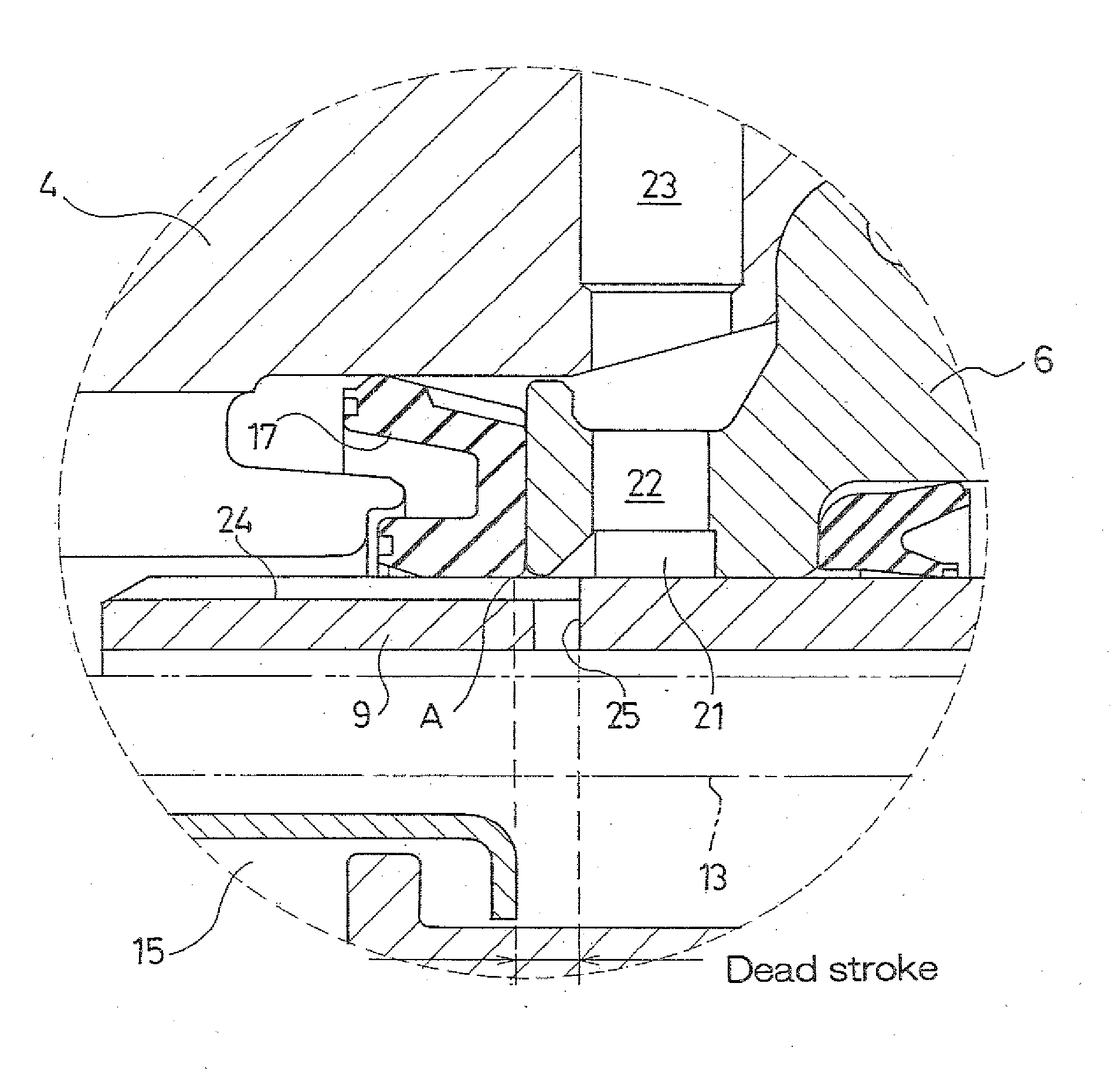
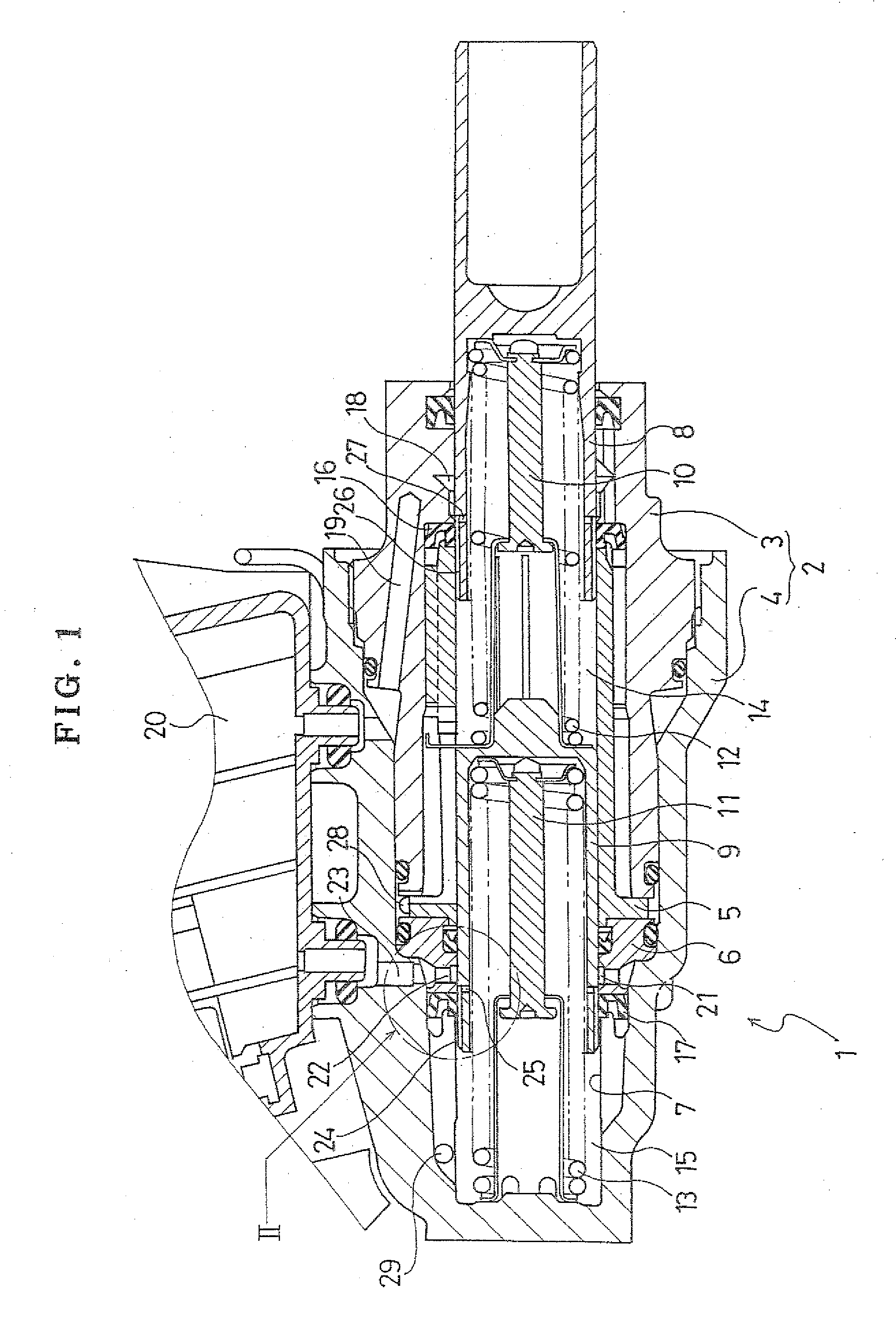
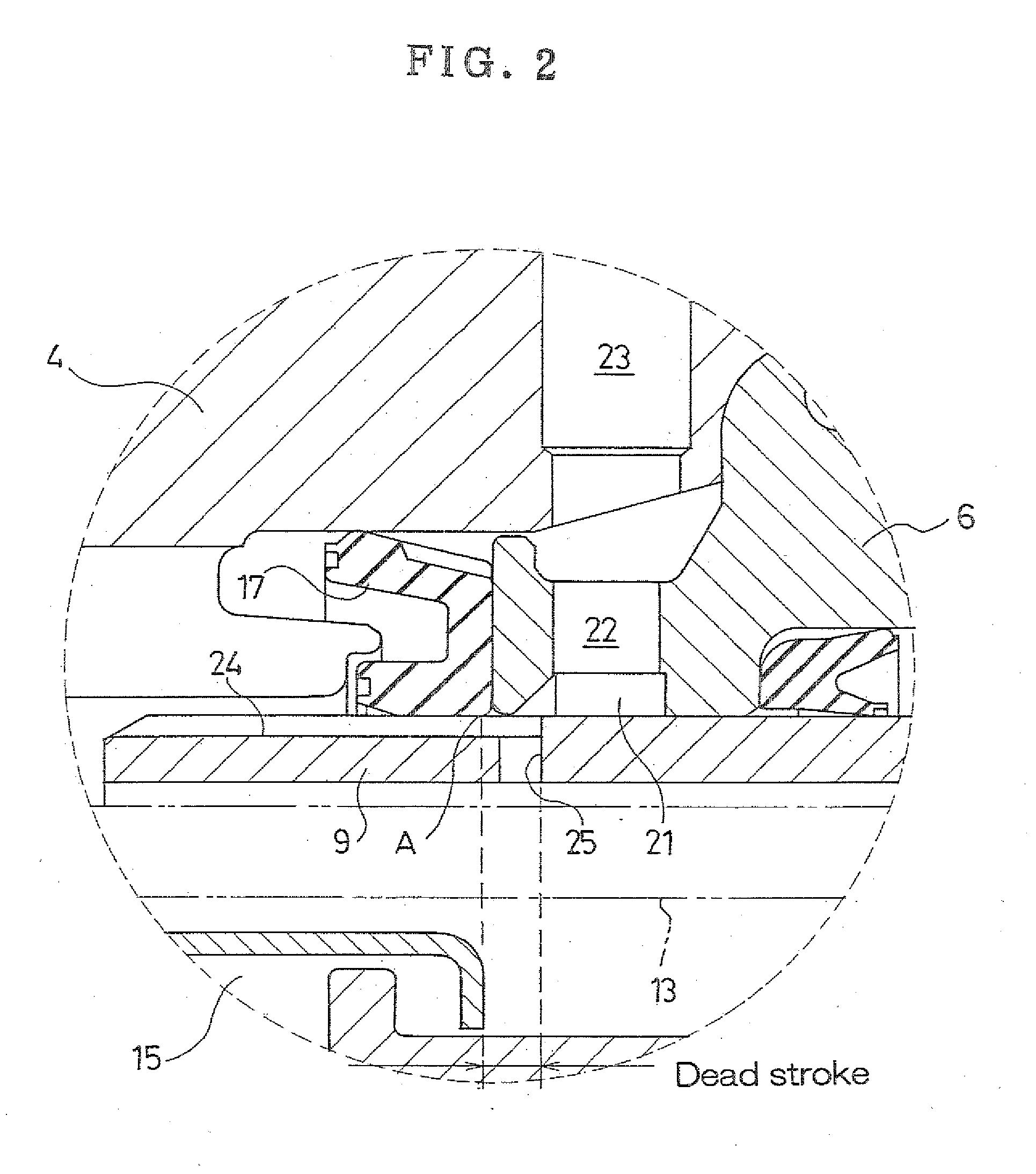
[0028]Hereafter, a best mode for carrying out the invention is described with reference to the attached drawings. Note that “front” and “rear” as referred in the description below refer, respectively, to the direction in which a piston moves when a master cylinder is operated and a direction in which the piston retracts when the operation of master cylinder is released. In the drawings referred to in each description, the “front” and the “rear” correspond to “left” and “right”, respectively.

[0029]FIG. 1 is a longitudinal sectional view of an example of an embodiment of the master cylinder according to the invention.

[0030]As shown in FIG. 1, a master cylinder 1 of the example includes a cylinder housing 2 which includes a first cylinder member 3 and a second cylinder member 4 to which the first cylinder member 3 is fitted and secured. Furthermore, a first piston guide 5 and a second piston guide 6 are held between the first cylinder member 3 and the second cylinder member 4 in an axi...


PUM


Abstract

A master cylinder according to the invention has a predetermined number of second axial grooves formed on an outer peripheral surface of a tip portion of a secondary piston at predetermined intervals apart in a circumferential direction. Second radial holes are formed at the rear ends of some of the second axial grooves penetrate between the inner and outer peripheral surfaces of the piston. In an inoperative state, the rear ends of the second axial grooves and the second radial holes are all located to the rear of a seal point of a second cup seal, and a second fluid supply chamber is connected to a second hydraulic pressure chamber via the second axial grooves and the second radial holes. When the rear ends of the second axial grooves and the second radial holes are all moved in front of the seal point, the second fluid supply chamber is disconnected from the second hydraulic pressure chamber. Consequently, brake fluid supply performance is ensured and the processing of the piston is simplified as well as piston strength being ensured.

Description

BACKGROUND ART[0001]The present invention relates to the technical field of a master cylinder which is used for a brake system of a vehicle such as an automobile and generates a master cylinder pressure to operate a brake. In particular, the invention relates to the technical field of a master cylinder that takes into account supply performance and self-support performance. The supply performance is the performance of supplying brake fluid to a hydraulic pressure chamber from a reservoir at the time of brake release and the self-support performance is the performance of drawing the brake fluid toward the hydraulic pressure chamber side of the master cylinder by driving an external power source such as a pump when the brake is operated, such as automatic braking, regardless of brake operation by a driver.[0002]For example, an automotive brake system is known that is provided with a master cylinder which is operated by depression of a brake pedal and generates a master cylinder pressu...

Claims


Application Information

Patent Timeline
Patent Type & Authority Applications(United States)
IPC IPC(8): B60T11/16
CPCB60T11/16B60T11/236B60T11/232B60T11/228
Inventor TAIRA, KAZUHISA
Owner BOSCH CORP
Why Eureka
Try Eureka