
Electrochemical sensor

a technology of electrochemical sensor and electrode, applied in the field of electrochemical sensor, can solve the problems of limited research on high pressure and high temperature electrochemistry, limited use of commercially available press-fit electrodes, and problems in the application of previously suggested electrode manufacturing methods

Active Publication Date: 2009-04-09
SCHLUMBERGER TECH CORP
View PDF9 Cites 46 Cited by
  • Summary
  • Abstract
  • Description
  • Claims
  • Application Information

AI Technical Summary

Benefits of technology

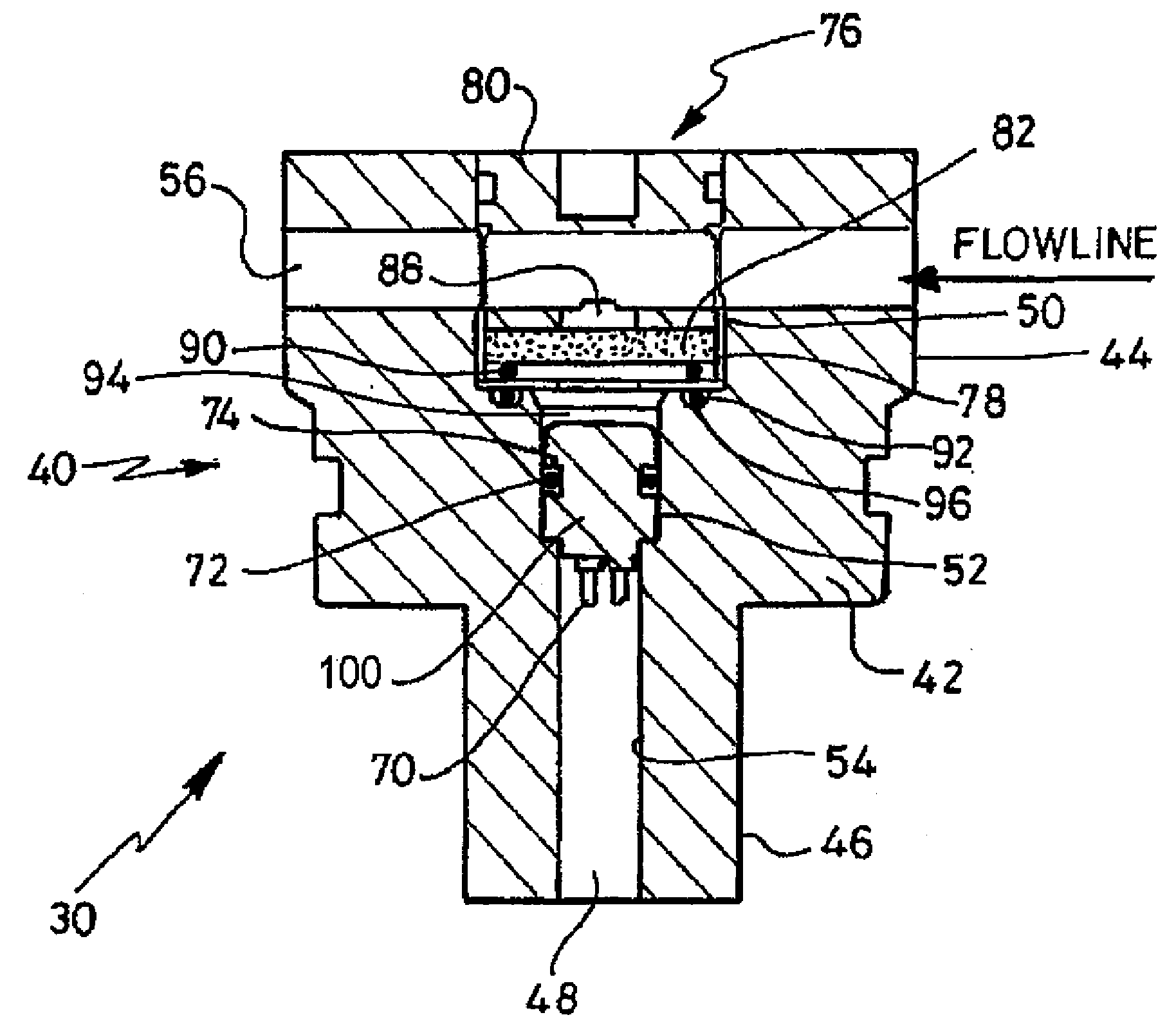
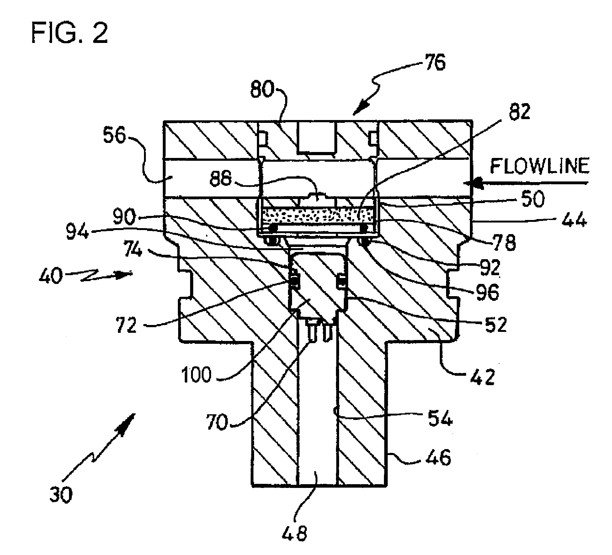
[0012]Thus, the conductive pin can be protected from direct contact with fluid or gas even if the fluid or the gas penetrates into the cylindrical housing when the electrode faces high pressure and high temperature conditions.

Problems solved by technology

However, to date, research on high pressure and high temperature electrochemistry has been limited by factors such as corrosion, thermoelectric effects and the decomposition of most polymeric materials.
Commercially available press fitted electrodes are limited to use mostly at ambient temperature and pressure conditions due to the eventual penetration of the electrolyte or sensing solution in addition to the wellbore fluids into the small gap found between the electrode materials and the main body.
However, it has recently been confirmed through experimental evaluations that the previously suggested electrode manufacturing methods have problems in applications in extreme wellbore conditions.
Designs that involve press-fitting and / or simple metal mounting procedures on top of electrical pin connectors have failed to obtain the much needed sensor stability and robustness, especially for high temperature and high pressure conditions.
Persistent creeping problems, where the liquid electrolyte penetrates into polymer sealant down to the electrical pin sections, have been consistently encountered.
This mechanical design failure results in increased background response, or unwanted peak signals related to metal stripping, thus rendering the sensing technique useless, especially at high pressure conditions.

Method used


Image

  • Electrochemical sensor
  • Electrochemical sensor
  • Electrochemical sensor

Examples


Embodiment Construction

[0027]The invention will be now described with reference to illustrative embodiments. Those skilled in the art will recognize that many alternative embodiments can be accomplished using the teachings of the present invention and that the invention is not limited to the embodiments illustrated for explanatory purposes.

[0028]It is to be noted that, in the explanation of the drawings, the same components will be given with the same reference numerals, omitting the repeated explanation.

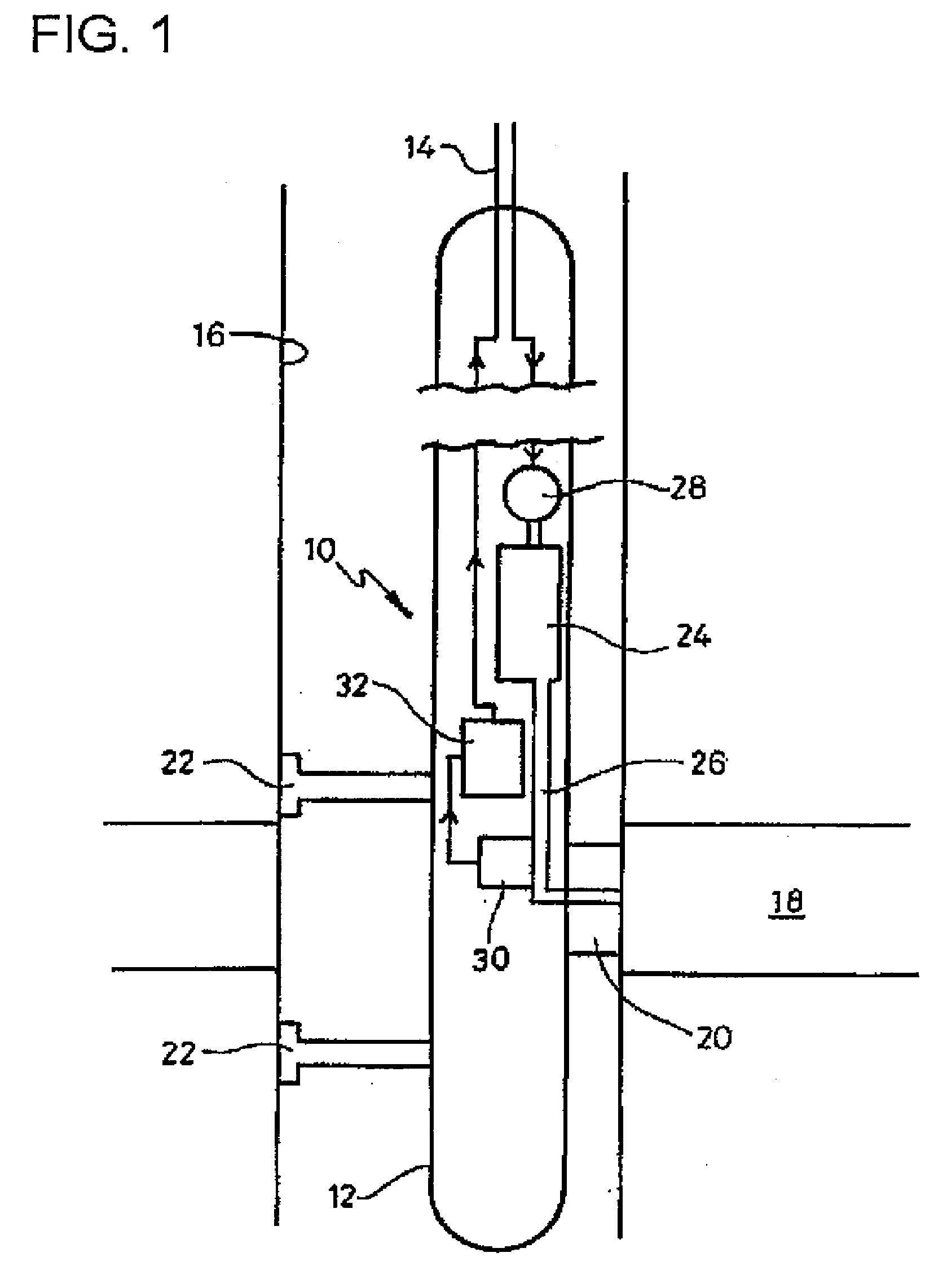
[0029]FIG. 1 shows the structure of a wellbore tool 10. The wellbore tool 10 is based on Schlumberger's Modular Dynamics Tester (MDT) (Schlumberger trademark), as described in U.K. patent publication number 2397651A. The wellbore tool 10 of the present embodiment is used for sensing or measuring contents of a specified component in hydrocarbons in a high pressure condition and / or a high temperature condition.

[0030]The tool 10 includes an elongate substantially cylindrical body 12, which in operation is su...


PUM

PropertyMeasurementUnit
anglesaaaaaaaaaa
pressureaaaaaaaaaa
circumferenceaaaaaaaaaa

Abstract

An electrochemical sensor for measuring contents of a fluid or gas at high pressure and / or high temperature, for use, for example, in a wellbore for hydrocarbon applications, is provided. The sensor includes: a bulkhead-like electrode assembly including a cylindrical housing and a cylindrical electrode structure. The cylindrical electrode structure includes a cylindrical conductive pin extending from a high pressure region to a low pressure region and an electrode connected to one end of the pin at the high pressure region and having an electrode surface for exposure to a flow path of the fluid or gas in the high pressure region. At least a part of the surface of the pin is protected from direct contact with the fluid or the gas by an insulating coating impermeable to the fluid or gas. The pin may include an alternating pattern of protruding and receded portions.

Description

BACKGROUND OF THE INVENTION[0001]The present invention relates to an electrochemical sensor operable at high temperature and / or high pressure conditions.[0002]Quantitative measurements and evaluation of wellbore fluids are important aspects of determining the quality and economic value of the well. More recently, studies aiming to characterize contents of corrosion-causing components such as H2S, CO2, pH and scale-forming ion species have been reported. This has been driven largely by the need to come up with effective mitigation of the severe impact of corrosion to both oil field operations and investments.[0003]Among the various techniques identified to measure the corrosion contents of wellbore fluids is electrochemical sensing. However, to date, research on high pressure and high temperature electrochemistry has been limited by factors such as corrosion, thermoelectric effects and the decomposition of most polymeric materials. As a result, there still is a great need for thermod...

Claims


Application Information

Patent Timeline
Patent Type & Authority Applications(United States)
IPC IPC(8): E21B47/00H01B5/00
CPCG01N33/241
Inventor TORIBIO, MICHAEL M.KAMIYA, AKIRAVANNUFFELEN, STEPHANEMATSUMOTO, NORIYUKILAWRENCE, JIMMY
Owner SCHLUMBERGER TECH CORP
Learn More