Sootblowing optimization for improved boiler performance

a technology of optimization and boiler performance, which is applied in the direction of boiler cleaning control devices, tableware washing/rinsing machines, solid removal, etc., can solve the problems of reducing boiler efficiency, reducing boiler efficiency, and reducing heat transfer efficiency of tubes

Active Publication Date: 2009-04-09
GENERAL ELECTRIC CO
View PDF1 Cites 24 Cited by
  • Summary
  • Abstract
  • Description
  • Claims
  • Application Information

AI Technical Summary

Benefits of technology

[0013]An advantage of the present invention is the provision of a soot cleaning control system that includes the use of boiler performance goals in a process for selecting soot cleaning devices for activation.
[0014]Another advantage of the present invention is the provision of a soot cleaning control system that includes a zone selection component for selecting a zone in the boiler for a soot cleaning operation and a soot cleaning selection component for selecting specific soot cleaning device(s) within the selected zone for activation.
[0015]These and other advantages will become apparent from the following description taken together with the accompanying drawings and the appended claims.

Problems solved by technology

Combustion deposits generally decrease the efficiency of the boiler, particularly by reducing heat transfer.
When combustion deposits accumulate on the boiler tubes, the heat transfer efficiency of the tubes decreases, which in turn decreases boiler efficiency.
However, this is not practical under actual operating conditions because cleaning is costly and creates wear and tear on boiler surfaces.
Injection of the cleaning medium can reduce boiler efficiency and prematurely damage heat transfer surfaces, particularly if they are over cleaned.
Boiler surface and water wall damage resulting from cleaning is particularly costly because correction may require an unscheduled outage of the power generating unit.
Accordingly, power generating plants typically maintain reasonable, but less than ideal boiler cleanliness levels.
These methods result in indiscriminate cleaning of the entire boiler or sections thereof, regardless of whether sections are already clean.
Developing these models can be challenging since the models are typically based upon rigorous first principle equations.
Finally, criteria-based methods focus on cleaning specific zones in the boiler, rather than improving overall boiler performance.
The above-described criteria-based methods do not relate boiler performance to a required level of heat transfer surface cleanliness and, therefore, to optimum operating parameters.
Accordingly, the approach assumes that required cleanliness levels for desired boiler performance goals are determined separately and provides no mechanism for selecting cleanliness levels for individual heating zones of the boiler.

Method used


Image

  • Sootblowing optimization for improved boiler performance
  • Sootblowing optimization for improved boiler performance
  • Sootblowing optimization for improved boiler performance

Examples


Embodiment Construction

[0026]The present invention is described herein with reference to “sootblowers” and the operation of “sootblowing.” However, it should be understood that the term “sootblower” as used herein refers to soot cleaning devices of all forms. Similarly, the term “sootblowing” as used herein refers to the soot cleaning operations associated with said soot cleaning devices.

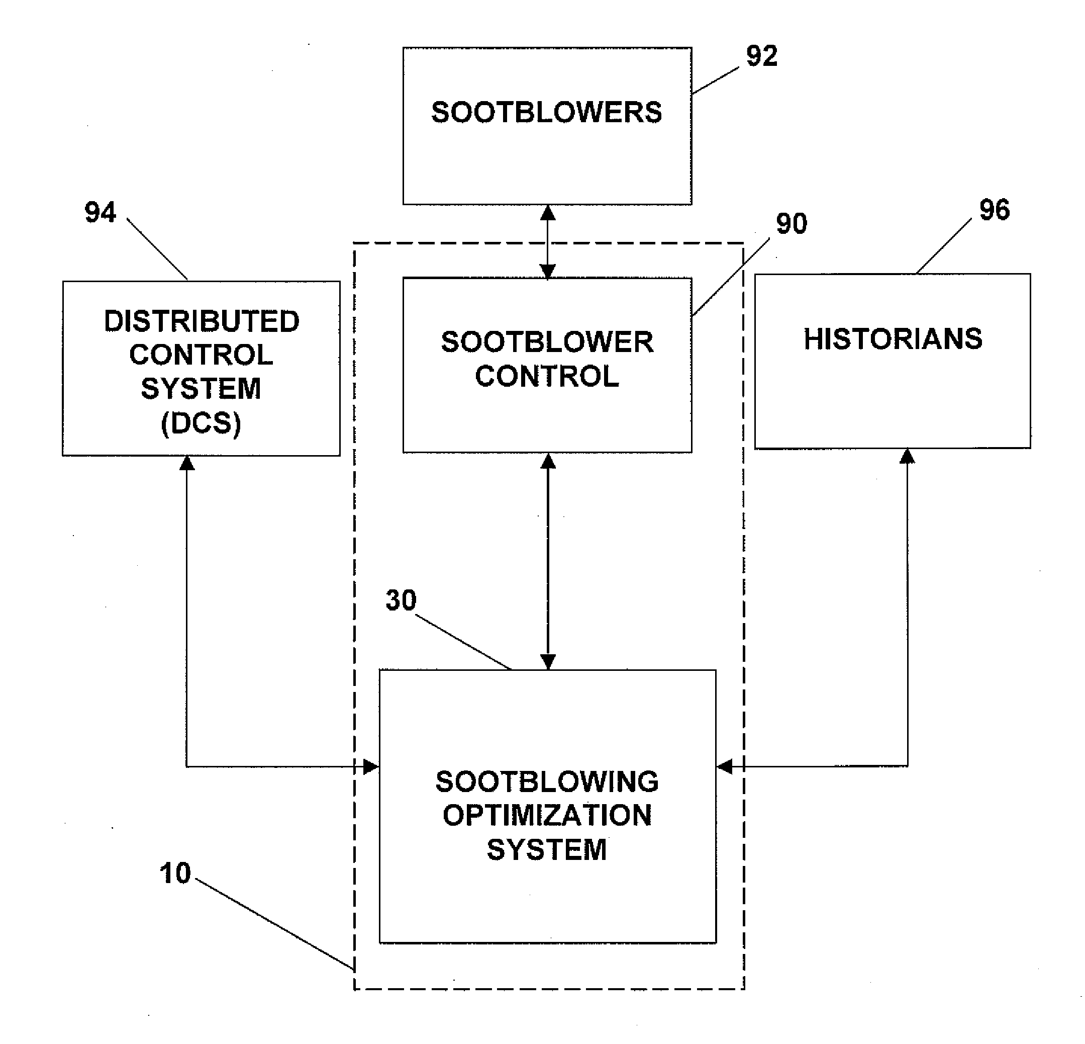
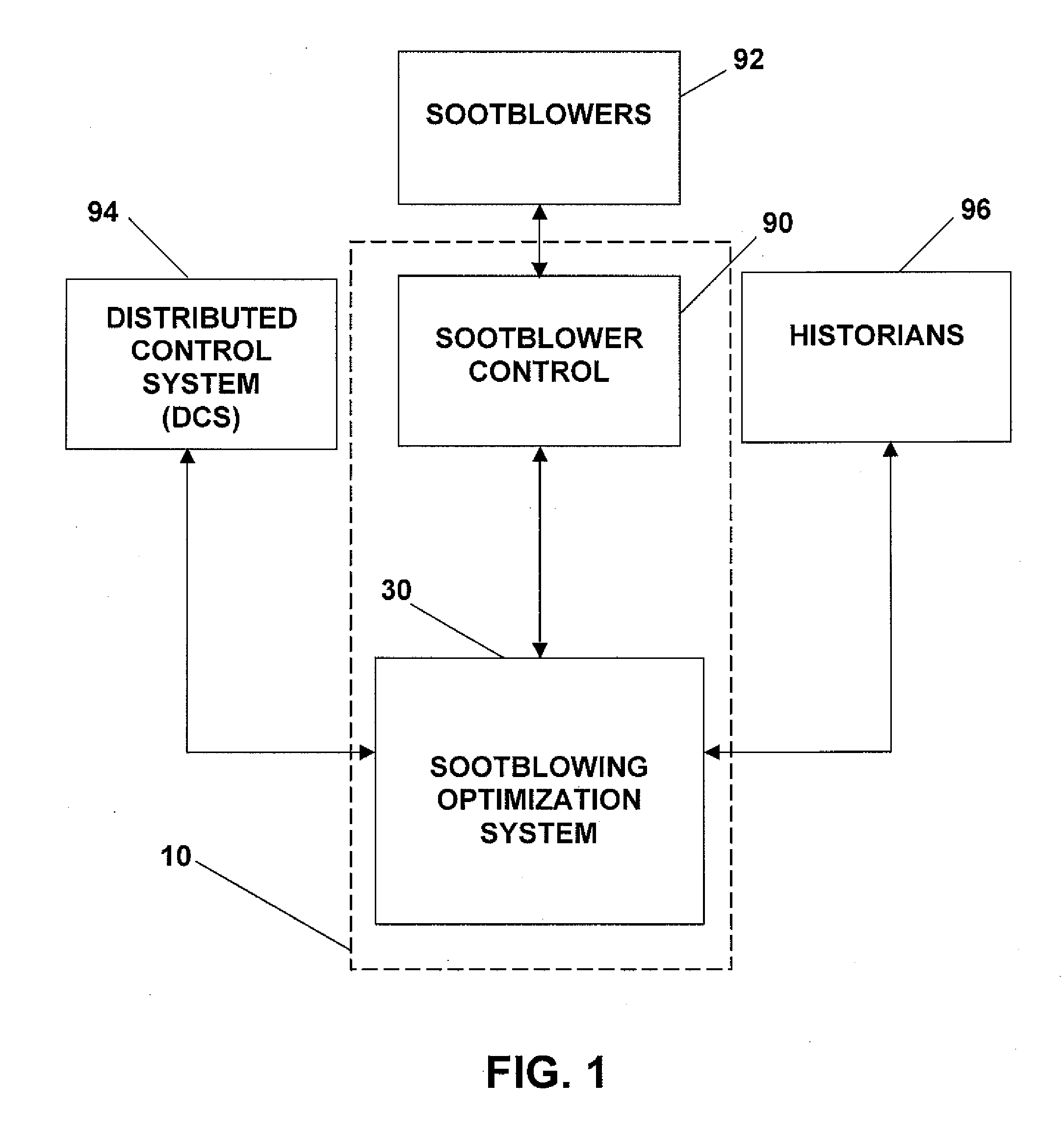
[0027]Referring now to the drawings wherein the showings are for the purposes of illustrating an embodiment of the present invention only and not for the purposes of limiting same, FIG. 1 shows a block diagram of a sootblowing control system 10 according to an embodiment of the present invention. Sootblowing control system 10 is generally comprised of a sootblowing optimization system 30 and sootblower control 90. As illustrated in FIG. 1, sootblowing control system 10 communicates with sootblowers 92, and other system components commonly used in power generation plants. Other system components may include, but are not li...


PUM


Abstract

A sootblowing control system that uses predictive models to bridge the gap between sootblower operation and boiler performance goals. The system uses predictive modeling and heuristics (rules) associated with different zones in a boiler to determine an optimal sequence of sootblower operations and achieve boiler performance targets. The system performs the sootblower optimization while observing any operational constraints placed on the sootblowers.

Description

GOVERNMENT LICENSE RIGHTS[0001]The U.S. Government has a paid-up license in this invention and the right in limited circumstances to require the patent owner to license others on reasonable terms as provided for by the terms of Contract No. DE-FC26-04NT41768, awarded by the United States Department of Energy.FIELD OF THE INVENTION[0002]The present invention relates generally to the operation of a fossil fuel-fired (e.g., coal-fired) boiler that is typically used in a power generating unit of a power generation plant, and more particularly to a system for optimizing soot cleaning sequencing and control in a fossil fuel-fired boiler.BACKGROUND OF THE INVENTION[0003]The combustion of coal and other fossil fuels in a power generating unit causes buildup of combustion deposits (e.g., soot, ash and slag) in the boiler, including boiler heat transfer surfaces. Combustion deposits generally decrease the efficiency of the boiler, particularly by reducing heat transfer. When combustion deposi...

Claims


Application Information

Patent Timeline
Patent Type & Authority Applications(United States)
IPC IPC(8): F22B37/48
CPCF22B37/48Y10T436/12F23J3/023F22B37/56
Inventor JAMES, JOHN ROBERTMCDERMOTT, JOHNPICHE, STEPHENPICKARD, FREDPARIKH, NEEL J.
Owner GENERAL ELECTRIC CO
Why Eureka
Try Eureka