
Uninterruptible Power Supply

Inactive Publication Date: 2009-04-09
FUJI ELECTRIC CO LTD
View PDF44 Cites 4 Cited by
  • Summary
  • Abstract
  • Description
  • Claims
  • Application Information

AI Technical Summary

Benefits of technology

[0009]In order to overcome the above issues, the present invention is to provide UPS that handles diverse output specifications regarding DC power source units while avoiding increasing numbers of models.
[0011]According to this aspect, the DC power source unit can be affixed to the AC power source unit later in response to a user's request. This affixture provides a manufacturer an advantage in that small numbers of models for AC power source units are prepared, DC power source units are placed to these models later in response to a use's request, and then these are shipped. This advantage enhances production efficiency and inventory management efficiency.
[0012]Further, a user has an advantage in that he / she purchases small numbers of models for an AC power source unit and purchases a DC power source unit later if it is necessary, enhancing economic efficiency and maintenance-management efficiency.
[0013]Further, the DC power source unit may be provided with a setting unit that sets a condition for starting power supply in response to an outside operation. This setting can make a single DC power source unit correspond to diverse specifications, efficiently solving the above mentioned issues.
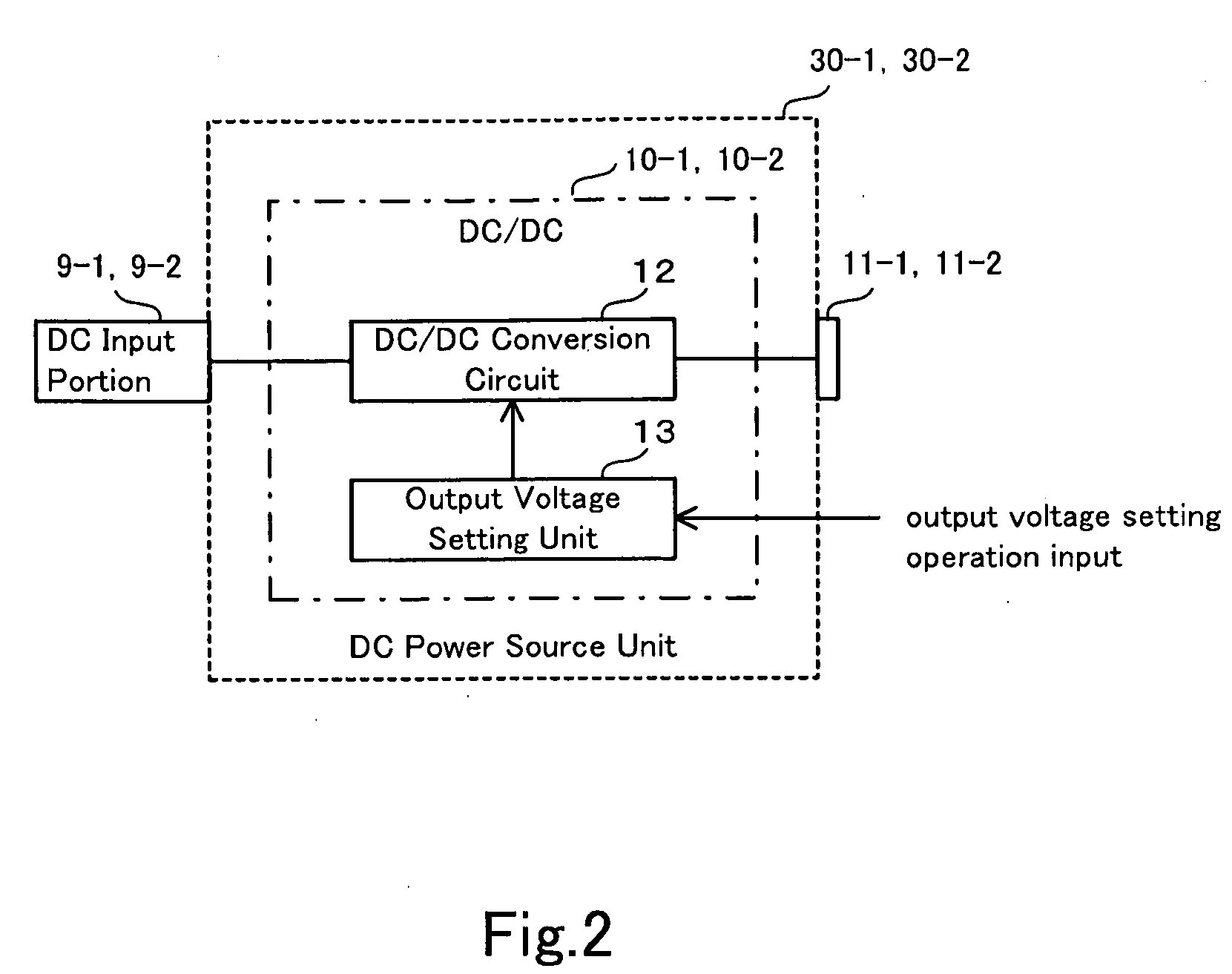
[0014]Further, the DC power source unit may be provided with a setting unit that sets a condition for starting power supply and the setting unit may include a DC / DC conversion circuit and an output voltage setting unit. The output voltage setting unit may control output voltage of the DC / DC conversion circuit depending on signals outputting from a controller. These additional circuit and unit automatically control output voltage, further enhancing user's conveniences.
[0015]According to the above aspect of the invention, a new UPS can response to diverse output specifications of DC power source units while avoiding increase of numbers of models.

Problems solved by technology

UPS, including both AC and DC power source portions shown in the patent document 1, however, must respond to diverse requests of specifications regarding a DC power source portion, causing a problem in that a manufacturer has to manufacture varieties of many models and stock them, reducing production efficiency and inventory-management efficiency.
On the other hand, a user has to purchase diverse models and manage them, facing a problem in that economic efficiency and maintenance-management efficiency are lowered.
Hence, such varieties of output specifications of DC power source units are a main cause of increasing numbers of models.

Method used


Image

  • Uninterruptible Power Supply
  • Uninterruptible Power Supply
  • Uninterruptible Power Supply

Examples


first exemplary embodiment

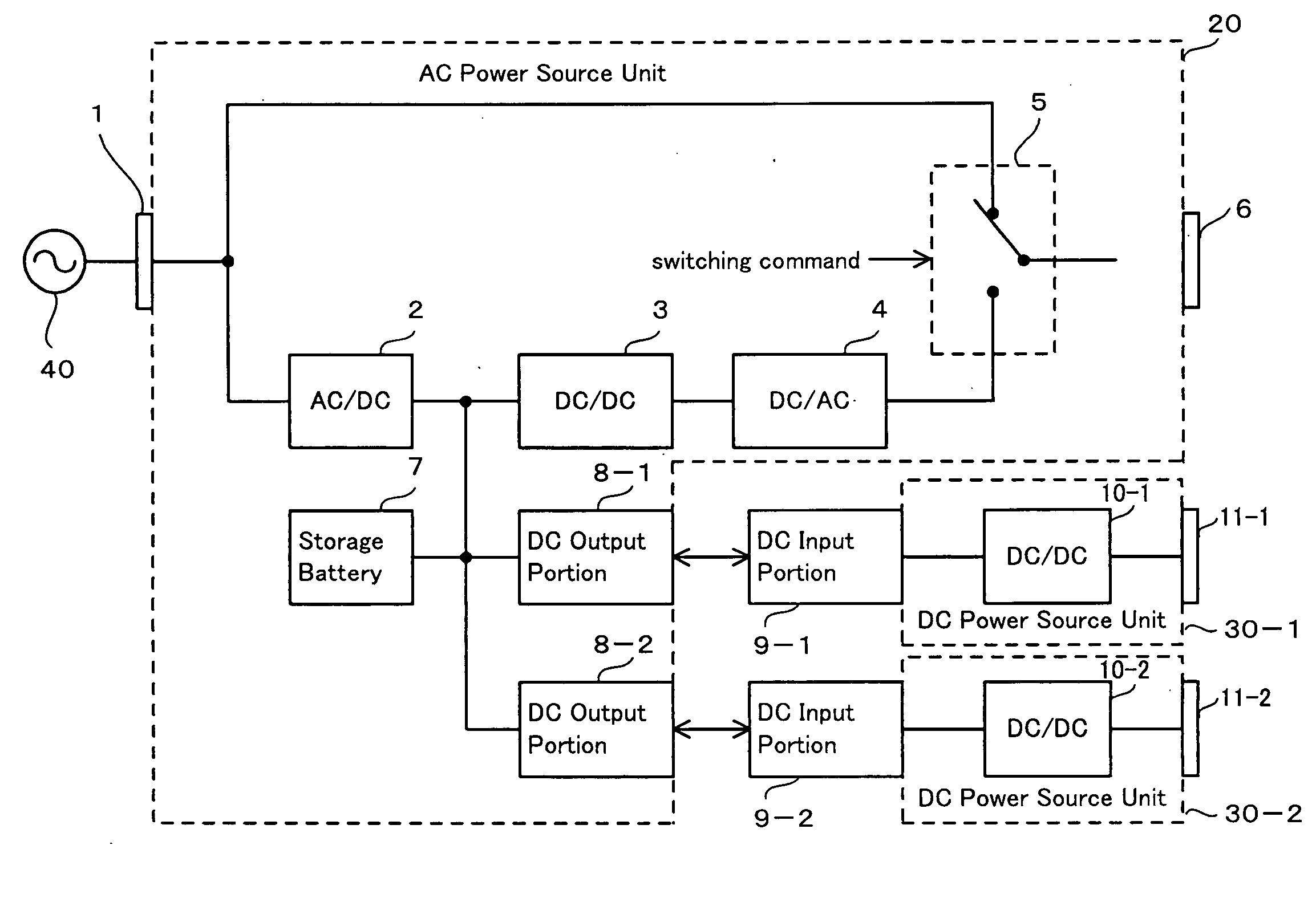
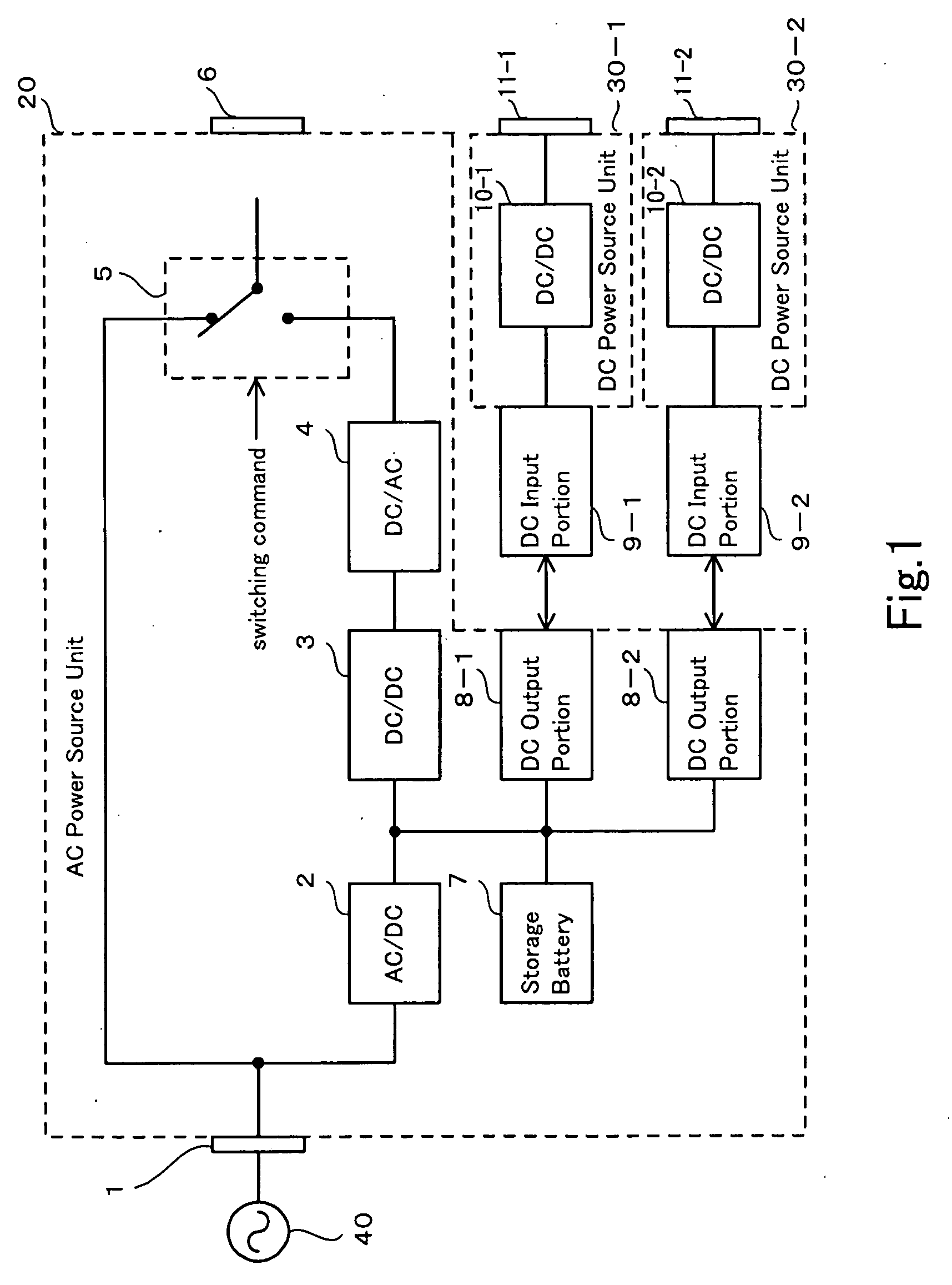
[0024]UPS in a first exemplary embodiment will be explained with referring to FIG. 1 and FIG. 2. FIG. 1 is a schematic view of UPS in the first exemplary embodiment. FIG. 2 is a structural view of a DC power source unit in UPS of the first exemplary embodiment.

[0025]UPS of the first exemplary embodiment comprises an AC power source unit 20, a DC power source unit 30-1 and a DC power source unit 30-2. The DC power source unit 30-1 and the DC power source unit 30-2 are placed in a container different from other container containing the AC power source unit 20. The AC power source unit 20, the DC power source unit 30-1 and the DC power source unit 30-2 are formed as detachable.

[0026]Namely, according to UPS of the exemplary embodiment, an AC input unit 1 is connected to an AC power source unit 40. An AC current of the AC power source unit 40 is converted to a DC current by an AC / DC converter 2 and stored in a storage battery 7 at normal time (non power interruption.) Further, when perf...

second exemplary embodiment

[0032]UPS in the second exemplary embodiment will be explained with referring to FIG. 3 and FIG. 4. FIG. 3 is a schematic view of UPS in the second exemplary embodiment. FIG. 4 is a structural view of a DC power source unit in UPS of the second exemplary embodiment. Here, the same numerical references are applied to the same constituents in the first exemplary embodiments.

[0033]In the first exemplary embodiment, DC power source units 30-1 and 30-2 output the DC current by using the DC current in the storage battery 7. On the other hand, in the second exemplary embodiment, DC power source units 31-1 and 31-2 output a DC current by using an AC current output by the AC output unit 6. Namely, the AC current, branched between the switching unit 5 and the AC output unit 6, is output to the AC output portions 14-1 and 14-2.

[0034]AC input units 15-1 and 15-2 of DC power source units 31-1 and 31-2 are detachably connected to AC output portions 14-1 and 14-2 of the AC power source unit 21. De...

third exemplary embodiment

[0037]The third exemplary embodiment will be explained, with referring to FIG. 5 and FIG. 6. FIG. 5 is a schematic view of the third exemplary embodiment. FIG. 6 is a structural view of a DC power source unit in the third exemplary embodiment.

[0038]In first and second exemplary embodiments, the output voltage setting unit 13 is placed and a user sets a desirable output voltage value to DC power source units 30-1, 30-2, 31-1 and 31-2 by inputting the output voltage operation. But, in the third exemplary embodiment, other control function (or a controller) instead of the output voltage setting unit 13 is placed, making it possible for a user to perform desirable setting more than set the output voltage value to an arbitrary value.

[0039]For example, as shown in FIG. 5, a power interruption message sending unit 50, detecting power interruption and automatically sending the message to a manager located far away from the location of the unit, is connected to the DC power source unit 30. I...


PUM


Abstract

The invention is to provide an uninterruptible power supply that is able to response to diverse output specifications of DC power source units while avoiding increase of numbers of models. DC power source units 30-1 and 30-2 are placed in a container different from other container that contains an AC power source unit 20 and the AC power source unit and the DC power source unit are detachable. Further, the DC power source units 30-1 and 30-2 is provided with a setting unit that sets a condition for starting power supply in response to outside operation.

Description

CROSS REFERENCE TO RELATED APPLICATIONS[0001]The present application claims priority from Japanese Patent Application No. 2007-260185 filed on Oct. 3, 2007, the contents of which are incorporated herein by reference.BACKGROUND OF THE INVENTION[0002]1. Field of the Invention[0003]The present invention relates to an uninterruptible power supply, including both an alternating-current (AC) power source unit and a direct-current (DC) power source unit and supplying an AC power or a DC power at the time of power interruption.[0004]2. Description of Related Art[0005]An uninterruptible power supply (abbreviated as UPS hereafter) for supplying electric power at the time of power interruption is widely utilized. In a computer system in particular, it is necessary to place a backup power source such as UPS in order to avoid a system's crash at the time of power interruption. Various kinds of UPS are prepared for electric apparatuses that need a backup power source. As an example of UPS, there ...

Claims


Application Information

Patent Timeline
IPC IPC(8): H02J7/34
CPCH02J9/00H02J1/00H02J7/34
Inventor SOEDA, KOUICHIOKANO, KOUJIKISHIMOTO, EIGOHASHIMOTO, TAKESHI
Owner FUJI ELECTRIC CO LTD
Learn More