
Method and device for generating a structure-free fiberscopic picture

a technology of structure-free fibers and generating devices, which is applied in the direction of instruments, optical elements, bundled fibre light guides, etc., can solve the problems of inadequate use of these devices, many applications in the field of diagnostics, inspection, quality assurance and research, and improve the optical impression of recorded images. , to achieve the effect of fast real-time processing and high quality

Inactive Publication Date: 2009-04-09
FRAUNHOFER GESELLSCHAFT ZUR FOERDERUNG DER ANGEWANDTEN FORSCHUNG EV +1
View PDF7 Cites 49 Cited by
  • Summary
  • Abstract
  • Description
  • Claims
  • Application Information

AI Technical Summary

Benefits of technology

[0019]The present invention is here based on the finding that an image free from interfering structures may be generated by means of a fiber bundle of a plurality of fibers and a sensor, if imaging parameters are provided for the system of fiber bundle and sensor which describe the geometrical characteristics of the intensity course generated by each individual optical fiber on the sensor. In an image reconstruction, for each individual fiber an amplitude value and / or luminosity information is generated by a function of the amplitude value and the imaging parameters of the corresponding fibers being adapted to an intensity picture of the sensor so that an optimum amplitude and / or luminosity value may be generated considering the geometrical imaging characteristics for each individual fiber. The imaging parameters here describe the geometrical form of the intensity distribution as it is caused by each individual fiber on the sensor. The imaging parameters may here for example be determined by a calibration to be performed once, wherein the fiber bundle is homogeneously illuminated and wherein a parameterization is adapted to the individual intensity courses of the individual fibers. This has the big advantage that by adapting a parameterization the coordinates of the fiber center and / or the center of the imaging of a fiber on the sensor may be determined with an accuracy which basically depends on the statistics (i.e. on the illumination intensity and the illumination time) and which may by far exceed the accuracy and / or the spatial resolution of the individual pixels of a sensor.
[0022]By adapting and / or fitting a predetermined calibration function for each individual fiber during image reconstruction it is thus guaranteed, that the actual imaging characteristics of each fiber are used to determine a luminosity value for each fiber. Thus, no luminosity corruptions may occur by summing up wrong pixels actually not belonging to the imaging of the fiber. In addition to that it is guaranteed by the calibration that the position of the fiber centers is known with an accuracy which by far exceeds the size of the individual pixels. The individual pictures thus offer an excellent spatial resolution and amplitude and / or luminosity values determined with greatest possible precision.
[0024]In one embodiment of the present invention, the image is imaged or mapped, respectively, by means of a fiberoptical system consisting of many individual optical fibers to an imaging sensor such that the intensity course caused by an individual fiber on the surface of the sensor has a spatial extension which is greater than one single light sensitive element and / or pixel of the sensor. This has the advantage, that the mapping or imaging parameters, respectively, which indicate the imaging location of the optical fiber on the sensor may be determined clearly more accurate than the geometrical extension of a pixel, as the same is determined by forming a center and / or fitting a suitable function to the intensity course which is measured by means of several pixels.
[0025]The same statistical effect is used in motion compensation, as in the detection of the movement / motion several image points each belonging together are used, so that an estimation of a motion vector from image to image may be performed with an accuracy which exceeds the intrinsic resolution, i.e. the spacings of adjacent image points.

Problems solved by technology

Without the imaging use of endoscopes, today many applications among others in the fields of diagnostics, inspection, quality assuring and research would be unthinkable.
As with acceptable diameters of the complete fiber bundle no randomly high number of individual fibers is possible and individual fibers cannot be produced with arbitrarily low diameters, hitherto especially the bad resolution of the transmitted image data and the architecture conditioned honeycomb structure of such a system inhibits an adequate use of these devices.
Maskings here have the disadvantage that they do improve the optical impression of the recorded image, but do not increase the accuracy by which the imaging location may be determined.
By this method, a wrong imaging is prevented as it is caused by non-parallel fibers in the fiber bundle, this way, however, no resolution increase may be achieved.
Methods of the prior art for image processing an image recorded by means of a fiberoptical system have the disadvantage here that the illustration quality and / or the subjective quality of perception of the pictures is improved, that the same do not cause an actual increase of resolution, however, as for increasing the resolution an introduction of additional (image) information is needed.
In fiberoptical systems which are used for diagnostics, the object and / or the shape of the object to be observed is usually not known a priori, however, so that such methods are not generally possible.
The method described there and other methods corresponding to the prior art have the big disadvantage here that the localization of the fiber centres on the sensor may only take place with pixel accuracy, i.e. with the accuracy predetermined by the size of an individual light-sensitive pixel.
A localization of the fiber centers underlying the motion compensation with pixel accuracy thus inevitably leads to a resolution which remains far below the possible theoretical value.
In addition to that, the summation of the light-intensities in a circular range around a central pixel is only restrictedly suitable to describe the complete intensity transmitted by an optical fiber.
For example, a deviation from a circular geometry of the light point as it may occur when an individual fiber and / or the fiber bundle comprises an angle relative to the sensor leads to the overall intensity not being determined correctly.

Method used


Image

  • Method and device for generating a structure-free fiberscopic picture
  • Method and device for generating a structure-free fiberscopic picture
  • Method and device for generating a structure-free fiberscopic picture

Examples


Embodiment Construction

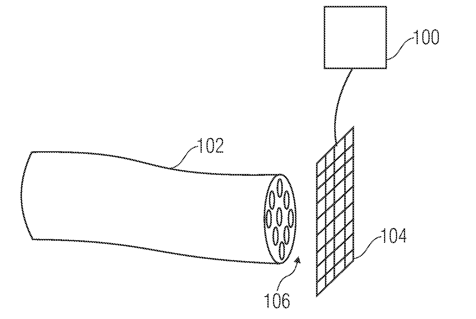
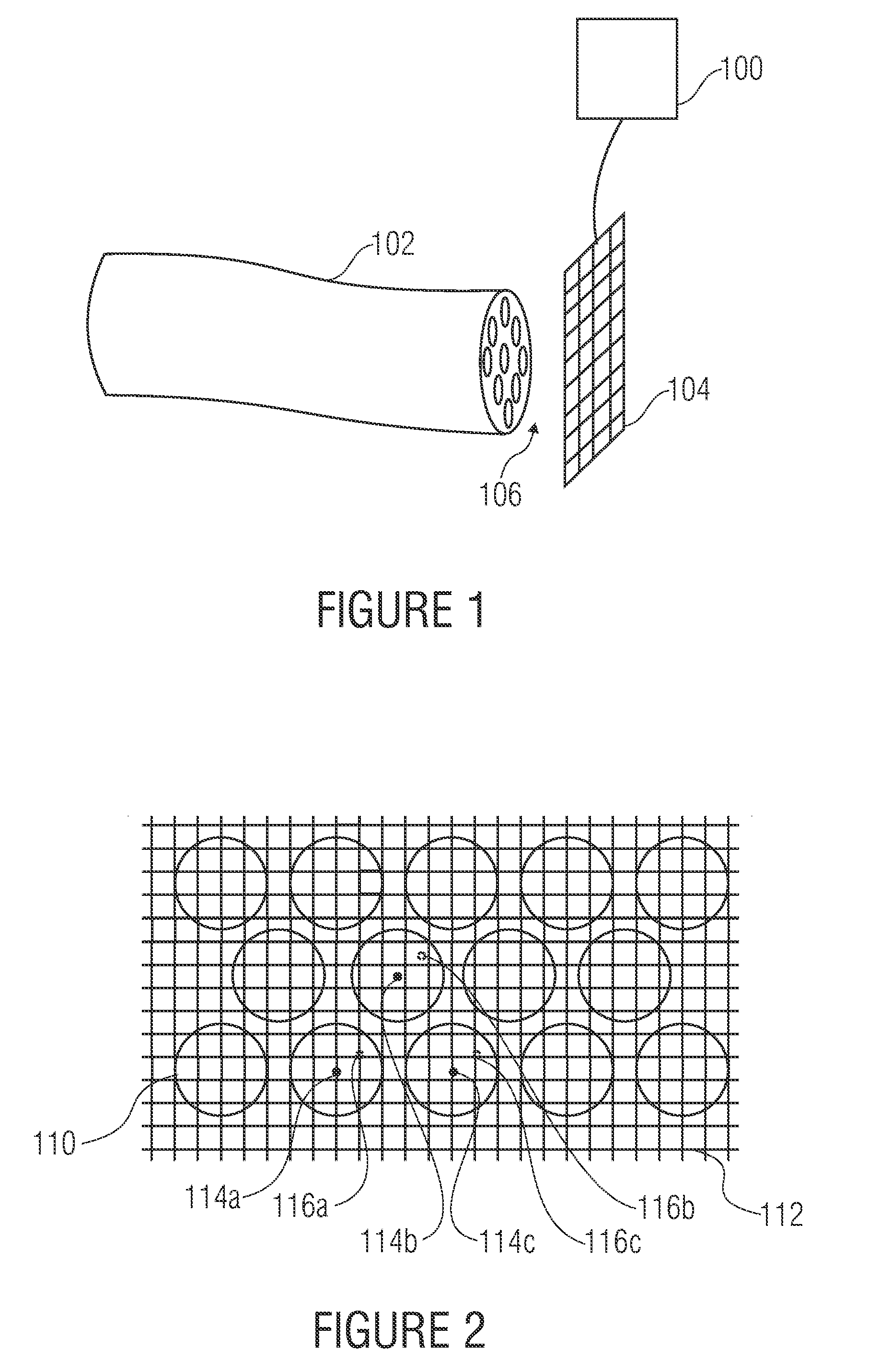
[0045]FIG. 1 shows an example for a system having a device for generating a high resolution image and / or an evaluation means 100. In addition to that, a fiber bundle 102 and a sensor 104 connected to the inventive evaluation means are shown, so that the same may on the one hand control the illumination times of the sensor 104 and on the other hand read out the image data of the sensor 104.

[0046]One image or object is imaged from the fiber bundle 102 which consists of a plurality of individual optical fibers 106 on the sensor 104.

[0047]The imaging situation of the individual optical fibers on the sensor is illustrated in detail with reference to FIG. 2, in which for reasons of clarity virtually circular intensity distributions (for example intensity distribution 110) are shown as they overlay for example in the square pixel matrix 112 of a CCD sensor.

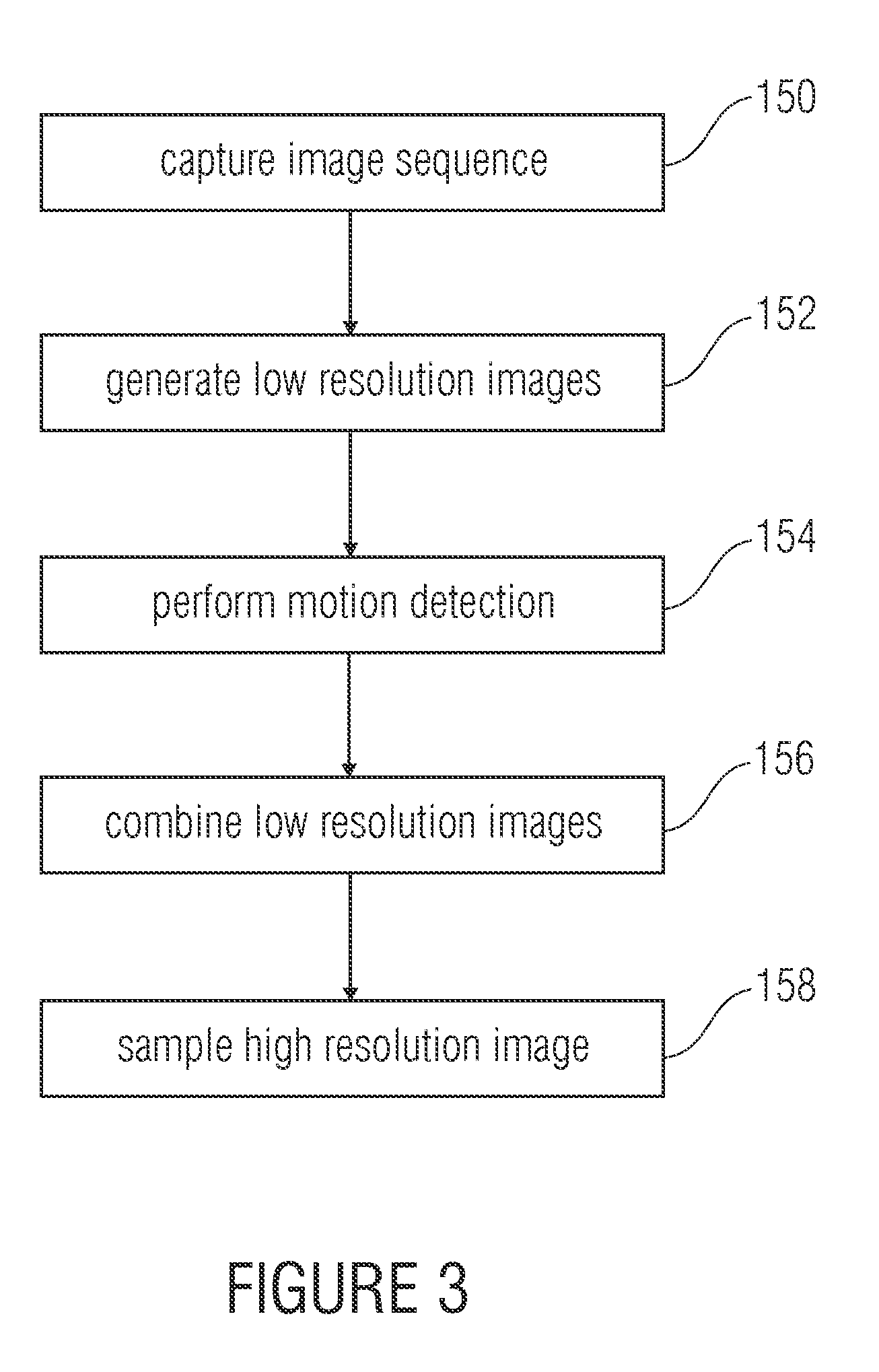
[0048]The functioning of a method for generating a high resolution image is now to be explained in more detail in the following with re...


PUM


Abstract

An image free from interfering structures may be generated by means of a fiber bundle of several optical fibers, when for the system of fiber bundle and sensor imaging parameters are provided, which describe the geometrical characteristics of the intensity course generated by each individual optical fiber on the sensor. In image reconstruction, for each individual optical fiber an amplitude value and / or luminosity information may be generated by fitting a function of the amplitude value and the imaging parameters of the respective optical fiber to an intensity picture of the sensor, so that an optimum amplitude and / or luminosity value may be generated considering the geometrical imaging characteristics for each individual optical fiber.

Description

BACKGROUND OF THE INVENTION[0001]The present invention relates to a device and a method providing the possibility, by means of fiberoptical systems, to generate interference-free images and relates in particular to how the picture of an imaging system, wherein an image is imaged to a sensor by means of a bundle of several orderly fibers, may operate in a suitable way to obtain an image without interfering structures.[0002]Optical systems in which an image is transferred to an imaging sensor via optics, are widely used. Without the imaging use of endoscopes, today many applications among others in the fields of diagnostics, inspection, quality assuring and research would be unthinkable. Here, on the one hand, systems of refractive optics (lens-optical systems) are used, i.e. systems with a rigid arrangement within which the image is transmitted to the sensor by an arrangement of lenses similar to a lens / objective of a camera. On the other hand, fiberoptical systems are used which con...

Claims


Application Information

Patent Timeline
IPC IPC(8): G02B6/06
CPCG02B23/26G06T3/4053G02B6/06G02B6/4298G06T17/20
Inventor DAUM, VOLKERSPINNLER, KLAUSCOURONNE, ROBERTELTER, MATTHIASRUPP, STEPHANWINTER, CHRISTIAN
Owner FRAUNHOFER GESELLSCHAFT ZUR FOERDERUNG DER ANGEWANDTEN FORSCHUNG EV
Learn More