Joining method on a jet spinning machine, spinning device and jet spinning machine

a jet spinning machine and spinning device technology, applied in the direction of open-end spinning machines, yarn, textiles and papermaking, etc., can solve the problems of the spinning unit of the german patent publication, the inability to produce spun threads, and the inability to insert auxiliary threads

Inactive Publication Date: 2009-04-16
SAURER INTELLIGENT TECH AG
View PDF3 Cites 20 Cited by
  • Summary
  • Abstract
  • Description
  • Claims
  • Application Information

AI Technical Summary

Benefits of technology

[0008]The object of the invention is to e

Problems solved by technology

The spinning unit of German Patent Publication DE 3611050 A1 is not suitable for producing a spun thread with a true twist.
Inserting the auxiliary threads according to the disclosure of German Patent Publication DE 3611050 A1, from the side, is not possible when using jet spinning devices, which operate with a twist retaining mechanism and a hollow spinning cone.
During this preparation phase for thread connection, errors frequently occur which disturb the formation of a thread connection or even prevent it.
A further disadvantage is that the thr

Method used


Image

  • Joining method on a jet spinning machine, spinning device and jet spinning machine
  • Joining method on a jet spinning machine, spinning device and jet spinning machine
  • Joining method on a jet spinning machine, spinning device and jet spinning machine

Examples


Embodiment Construction

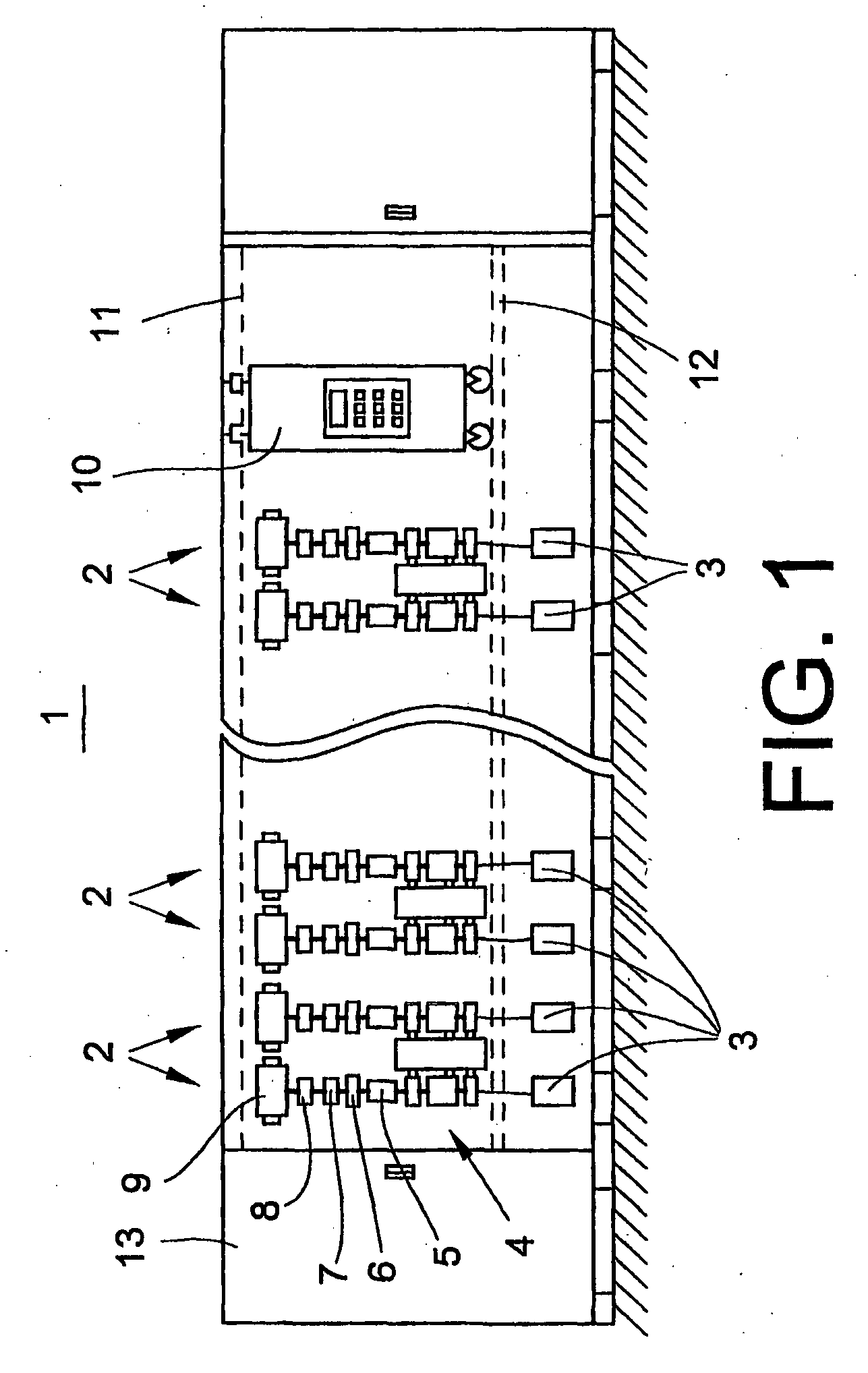
[0034]The jet spinning machine 1 shown in FIG. 1 has a plurality of spinning stations 2 arranged next to one another in a row. Each spinning station 2 comprises a fibre band source 3, which may be configured, for example, as a spinning can, a drawing frame 4, a spinning device 5, a pair of take-off rollers 6, a yarn clearer 7, a thread transfer mechanism 8 and a take-up bobbin configured as a cross-wound bobbin 9. An operating carriage 10 is guided along the spinning stations 2, on bars 11, 12. A drive unit 13 is arranged at one end of the jet spinning machine.

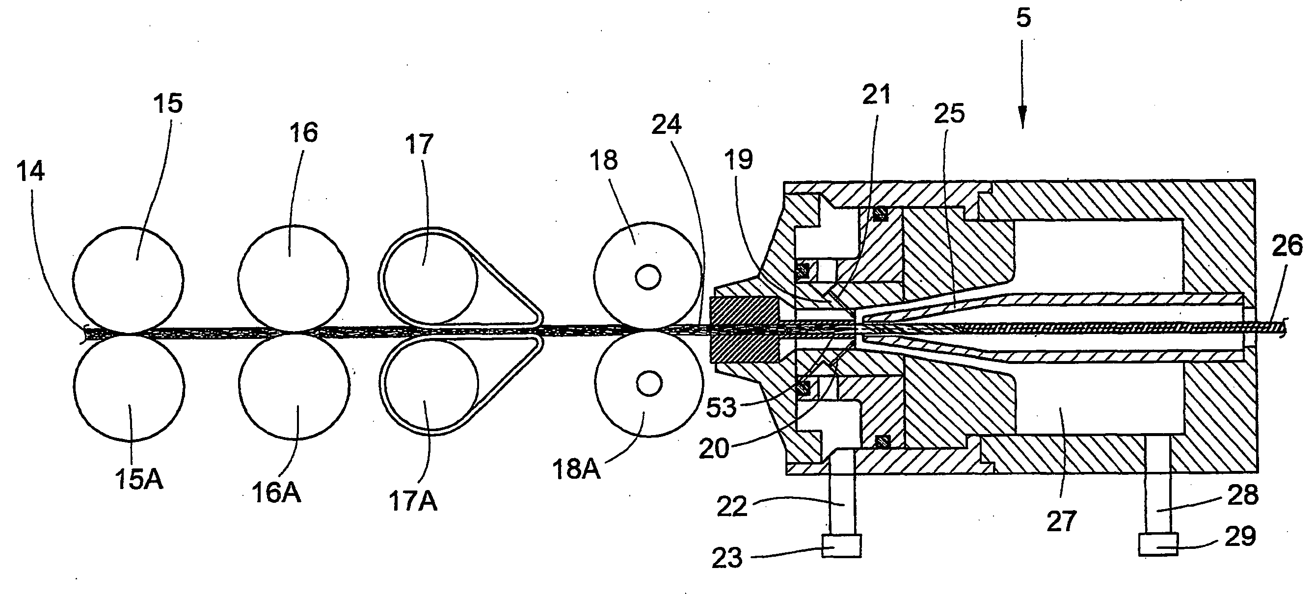
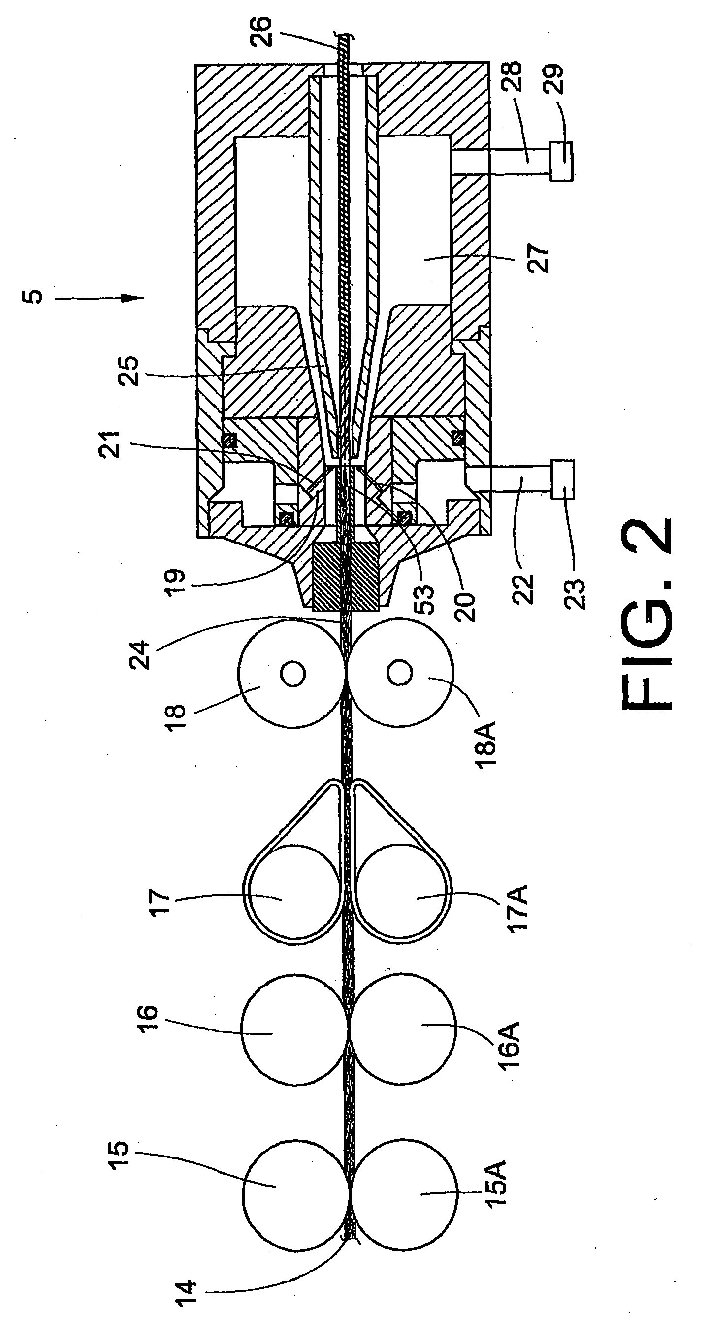
[0035]FIG. 2 shows a drawing frame with a subsequent spinning device 5 and the passage of fibres. The fibre band 14 drawn off from the fibre band source 3 is drawn in by the pair of upper and lower rollers 15, 15A arranged as feed rollers and drawn with the pairs of upper and lower rollers 16, 16A; 17, 17A; 18, 18A. A tweezer-like twist retaining mechanism 53 and a spinning nozzle mechanism 19 are arranged in a first component...


PUM

PropertyMeasurementUnit
Speedaaaaaaaaaa

Abstract

A joining method wherein fibers of a fiber band are wound around an auxiliary thread threaded into a spinning device and drawn through a spinning cone. The newly spun thread is separated from the auxiliary thread and connected to the end of an upper thread. A spinning device is provided for a jet spinning machine for carrying out such method, comprising a first clamping device for temporary clamping of the upper thread and a second clamping device for temporary clamping of the auxiliary thread. A jet spinning machine for carrying out the method has a mechanism for storing the auxiliary thread and the newly spun thread, a mechanism for separating the auxiliary thread from the newly spun thread, and a splicing mechanism for connecting the newly spun thread to the upper thread, all arranged only on at least one operating carriage displaceable along multiple spinning stations.

Description

CROSS-REFERENCES TO RELATED APPLICATIONS[0001]This application claims the benefit of German patent application 10 2005 022 187.4, filed May 13, 2005, herein incorporated by reference.BACKGROUND OF THE INVENTION[0002]The invention relates to a joining method on a jet spinning machine, as well as a spinning device and a jet spinning machine for carrying out the joining method.[0003]Jet spinning machines generally comprise spinning devices, to which a fibre band drawn to a fibre bundle is supplied from a drawing frame. The fibre band runs through a spinning nozzle, in which it is acted upon by swirling air currents and is thereby provided with a true torsion or true twist. Positioned downstream from the spinning nozzle is a hollow spinning cone, through which the fibre band is drawn off as a thread from an outlet opening and then wound onto a take-up bobbin as the upper thread.[0004]German Patent Publication DE 3611050 A1 describes a spinning unit, which is intended to produce bobbins ...

Claims


Application Information

Patent Timeline
IPC IPC(8): D01H4/50D01H1/115D02G1/00
CPCD01H1/115D01H15/002D01H4/02
Inventor WEIDE, THOMASFEUERLOHN, HELMUT
Owner SAURER INTELLIGENT TECH AG
Why Eureka
Try Eureka