
Turbocharger with adjustable turbine geometry and a vane carrier ring

a turbine geometry and adjustable technology, applied in the direction of gas turbine plants, machines/engines, engine controllers, etc., can solve the problems of friction between the guide vanes and the housing wall, wear-inducing friction between the guide vanes and the carrier ring, and the undesired pressing of the opposite housing wall, so as to increase the service life reduce the housing wall, and increase the efficiency of the exhaust gas turbocharger

Inactive Publication Date: 2009-04-16
DAIMLER AG
View PDF0 Cites 18 Cited by
  • Summary
  • Abstract
  • Description
  • Claims
  • Application Information

AI Technical Summary

Benefits of technology

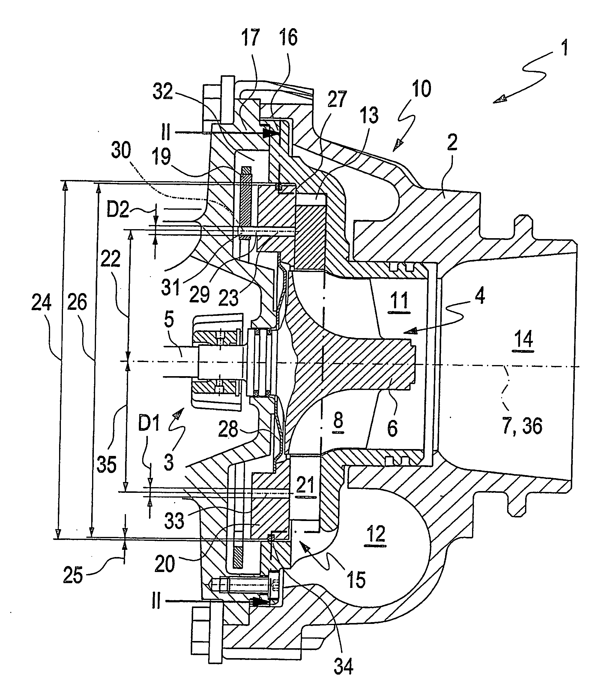
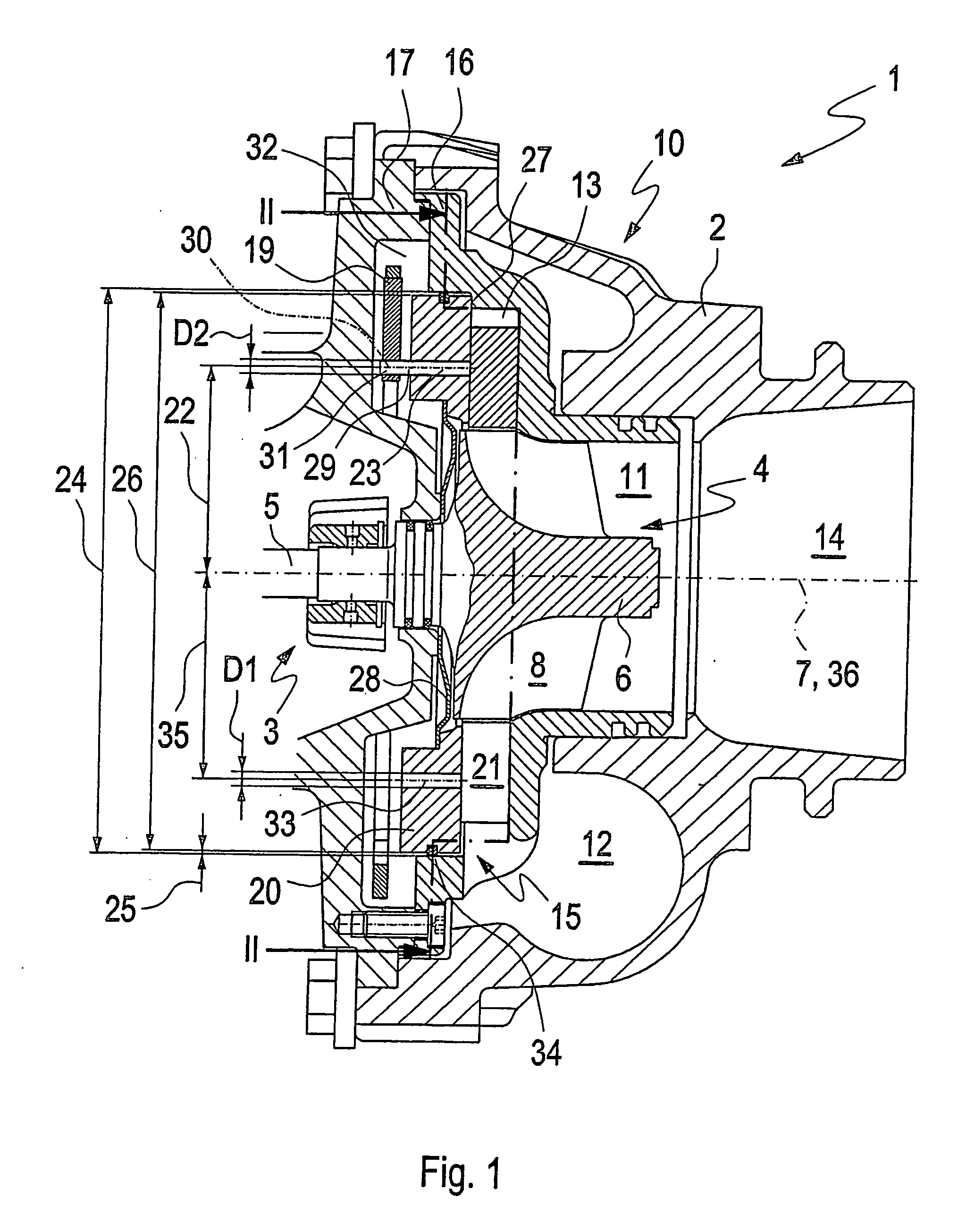
[0007]This pressure difference generates a force in the axial direction on the support shafts of the guide vanes, so that an axial movement of the movably mounted guide vanes occurs as a result of a cold clearance. Thus, the guide vanes are on occasion pressed against an opposite housing wall in an undesired manner. An adjustment movement of the guide vanes then leads to wear-inducing friction between the guide vanes and the housing wall. If, on the other hand, the pressure in the rear chamber is lower than in the inflow passage, in particular under medium and high loads of the internal combustion engine, a force acting in the axial direction is also generated on the guide vane surfaces located opposite the wall, so that the guide vanes are now pressed against the carrier ring. In this case any position adjustment of the guide vanes causes friction between the guide vanes and the carrier ring. Accordingly, increased abrasion again occurs, so that wear of the exhaust gas turbocharger is increased.
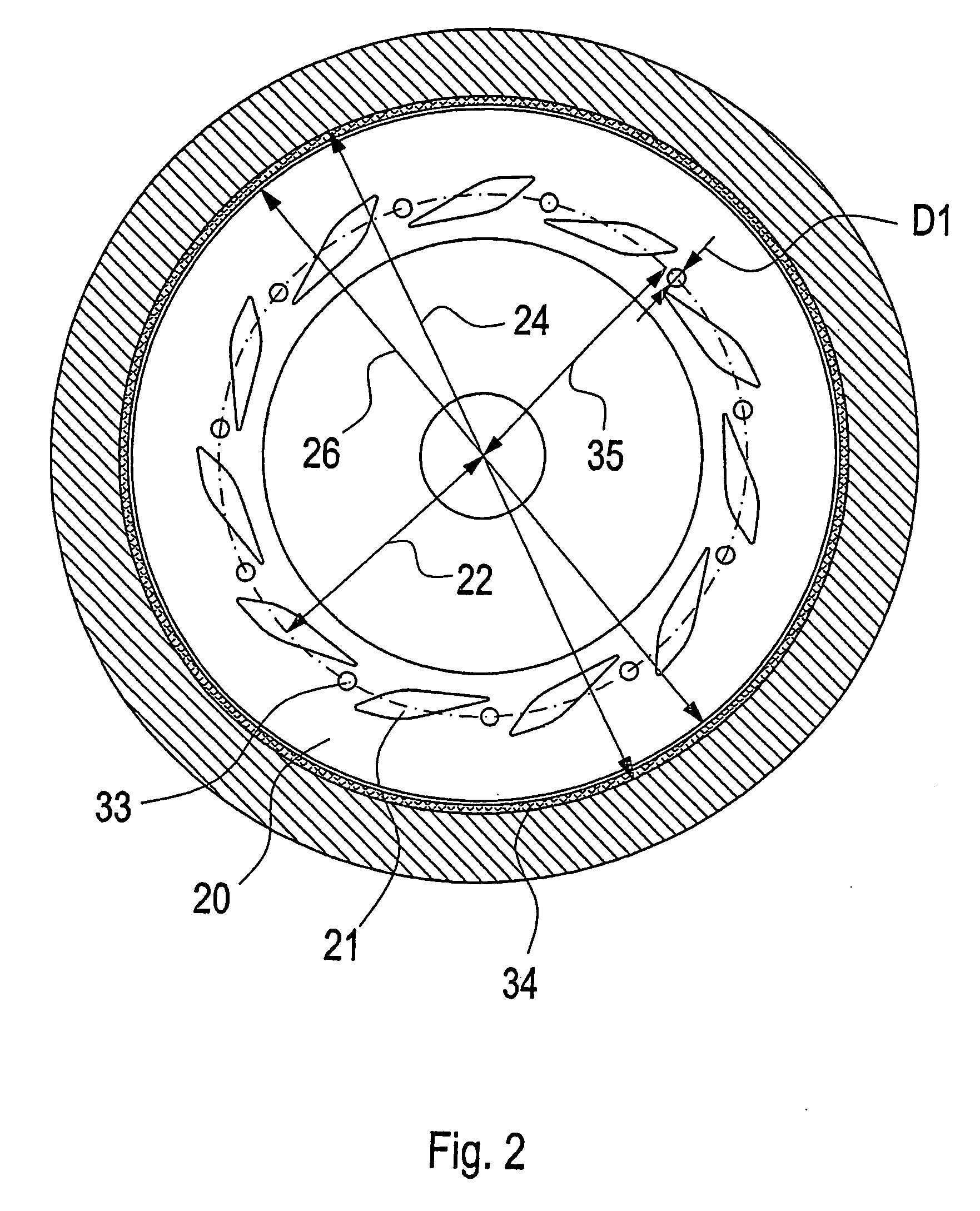
[0011]In a further configuration, the carrier ring has on an outer circumference a sealing device by which passage of the exhaust gas from the turbine spiral duct into the chamber upstream of the guide vanes is prevented. All the exhaust gas is therefore conducted by the spiral duct of the turbine via the guide vanes. A further increase in the efficiency of the exhaust gas turbocharger can be brought about thereby.

Problems solved by technology

Thus, the guide vanes are on occasion pressed against an opposite housing wall in an undesired manner.
An adjustment movement of the guide vanes then leads to wear-inducing friction between the guide vanes and the housing wall.
In this case any position adjustment of the guide vanes causes friction between the guide vanes and the carrier ring.
Accordingly, increased abrasion again occurs, so that wear of the exhaust gas turbocharger is increased.

Method used


Image

  • Turbocharger with adjustable turbine geometry and a vane carrier ring
  • Turbocharger with adjustable turbine geometry and a vane carrier ring
  • Turbocharger with adjustable turbine geometry and a vane carrier ring

Examples


Embodiment Construction

[0016]An intake system and an outlet system are associated with an internal combustion engine for a motor vehicle. The internal combustion engine is in the form of a diesel engine. The internal combustion engine has a housing with a cylinder head and a crankcase. Cylinders are arranged in the crankcase, each cylinder having an axially movable piston. In addition, a crankshaft is mounted rotatably in the crankcase. Each piston is connected to the crankshaft by means of a connecting rod, so that relevant piston forces can be transmitted to the crankshaft and converted into a rotary motion of the crankshaft. Combustion chambers for burning an air-fuel mixture are formed in the cylinders of the internal combustion engine. Each combustion chamber is delimited by an inner wall of a cylinder, by the piston being movable in the cylinder and by a wall of the cylinder head, the wall of the cylinder head and the respective piston being arranged approximately opposite one another. The volumes o...


PUM


Abstract

In an exhaust gas turbocharger for an internal combustion engine, which comprises a housing with an exhaust gas-conducting section with an inflow passage for directing exhaust gas to a turbine wheel arranged in the exhaust gas-conducting section including a carrier ring with an adjustable guide apparatus having guide vanes arranged on one side of the carrier ring for controlling the flow velocity of the exhaust gas flow to the turbine wheel, the carrier ring has at least one compensating opening extending therethrough so as to provide for pressure compensation between the inflow duct and a rear chamber which is arranged on a side of the carrier ring opposite the guide vanes.

Description

[0001]This is a Continuation-In-Part Application of pending International patent application PCT / EP2007 / 003088 filed Apr. 5,2007 and claiming the priority of German patent application 10 2006 018 055.0 filed Apr. 19, 2006.BACKGROUND OF THE INVENTION [0002]The invention relates to an exhaust gas turbocharger with an adjustable turbine geometry including an inlet vane structure and a vane carrier ring.[0003]The document WO 2004 / 022926 A1 discloses an exhaust gas turbocharger which comprises a housing with an exhaust gas-inlet section and a rotor with a turbine wheel, wherein an adjustable guide apparatus is arranged in the exhaust gas-inlet section. The exhaust gas-inlet section is designed for guiding the exhaust gas, for example of an internal combustion engine of a motor vehicle to the turbine wheel. The exhaust gas can be supplied via an inflow duct to the exhaust gas-inlet section and to the turbine wheel which is arranged in a turbine housing. For varying a flow velocity of the ...

Claims


Application Information

Patent Timeline
Patent Type & Authority Applications(United States)
IPC IPC(8): F02D23/00
CPCF01D3/00F01D3/025F05D2220/40F02C6/12F01D17/165
Inventor EISSLER, WERNERWEHINGER, FRANK
Owner DAIMLER AG
Learn More