Charging and rechargable devices

a rechargeable device and recharging technology, applied in the direction of capacitors, electric vehicles, transportation and packaging, etc., can solve the problems of high temperature between components, chargers and/or capacitors that cannot provide such rapid charge, damage to components, etc., to achieve rapid charge, increase the energy capacity of supply ultracapacitors, and increase the effect of charg

Inactive Publication Date: 2009-04-16
DEMAIN TECH
View PDF11 Cites 71 Cited by
  • Summary
  • Abstract
  • Description
  • Claims
  • Application Information

AI Technical Summary

Benefits of technology

[0016]wherein, in use, any charge in the supply ultracapacitor is rapidly distributed between the supply ultracapacitor and storage ultracapacitor when the rechargeable electrical device is mounted to the receiver thereby providing a rapid charge to the rechargeable electrical device.
[0017]Accordingly, the provision of the supply ultracapacitor in the charger allows the storage ultracapacitor to be rapidly charged by the charger. The supply ultracapacitor is charged by a charging power supply such as a battery, mains power supply or power device linked to the mains power supply. The supply ultracapacitor can therefore be left to charge in the charger, preferably to full capacity and thereafter, once the rechargeable electrical device is connected to the charger, the supply ultracapacitor can rapidly transfer the charge stored therein between the supply ultracapacitor and storage ultracapacitor.
[0019]For example, in one embodiment, the ratio of the energy capacity of the supply ultracapacitor to the energy capacity of the storage ultracapacitor can be selected to be between 50% to 200%. In this embodiment, a power source such as mains power or a battery is continuously charging the supply ultracapacitor. When the rechargeable electrical device is inserted into the charger, the energy will rapidly (in some cases almost instantly) even out between the supply ultracapacitor and the storage ultracapacitor resulting in the storage ultracapacitor being charged to between ⅓ (corresponding to the 50% ratio) to ⅔ (corresponding to the 200% ratio) of the storage ultracapacitors maximum charge capacity. Further charging is preferably accomplished using the power source such as a battery, mains power or the like which supplies an electrical trickle charge. In effect, the power source takes over charging the rechargeable electrical device, preferably over a brief period of time. The advantage of this system is that the charger can provide an instant charge to the rechargeable electrical device, preferably greater than 50% charge capacity of the rechargeable electrical device. This instant charge allows a user to go and work again while the supply ultracapacitor is recharged. A user can then use the charger to top up the charge in the storage ultracapacitor of the rechargeable electrical device.
[0020]Nevertheless, the greater the energy capacity of the supply ultracapacitor compared to the storage ultracapacitor, the more charge that is transferred to the storage ultracapacitor when each ultracapacitor is connected during charging. It is therefore preferable for the energy capacity of the supply ultracapacitor to be more than twice the energy capacity of the storage ultracapacitor. This results in the rechargeable electrical device being more rapidly charged to full capacity.
[0034]It is possible that the rechargeable device may move when mounted to the receiver. It is therefore preferable for the at least one electrical contact and the corresponding electrical terminal of the rechargeable device to be movable relative to each other while in engagement.
[0045]The rechargeable device can include a variety of different power storage means for storing power. In most embodiments of the present invention, the rechargeable device is configured to be rapidly charged. Accordingly, the power storage means of the rechargeable device includes at least one supply ultracapacitor electrically connected to the at least one electrical contact, the supply ultracapacitor being charged when the electrical charger is connected to a power source. The supply ultracapacitor allows for fast charging of the rechargeable device. The rechargeable device could include an energy storage pack for use with a powered device such as a powered tool in the form of a sander, power screwdriver, power drill, power saw, chainsaw, planer, router, grinder, polisher, rotary tool, light, powered knife or any other powered tool with which the rechargeable device could be suitable for use. The powered device may include other forms of portable powered devices such as audio and / or visual devices, computers, telephones or any other portable powered device with which the rechargeable device could be suitable for use. The rechargeable device could include any one the abovementioned devices themselves. It will be appreciated that the rechargeable device may take other suitable forms and have other suitable applications.

Problems solved by technology

While it is possible to charge a capacitor relatively quickly, in some cases to full capacity in less than 10 seconds, most existing types of chargers are not able to provide such a rapid charge.
If the contact between any two components is less than ideal, a high current can potentially cause arcing between these components, result in a high temperature between the components, possibly damaging the components, charger and / or capacitor.
The risk of a user being electrocuted can also increase if there is poor contact between two components conducting a high current.

Method used


Image

  • Charging and rechargable devices
  • Charging and rechargable devices
  • Charging and rechargable devices

Examples


Embodiment Construction

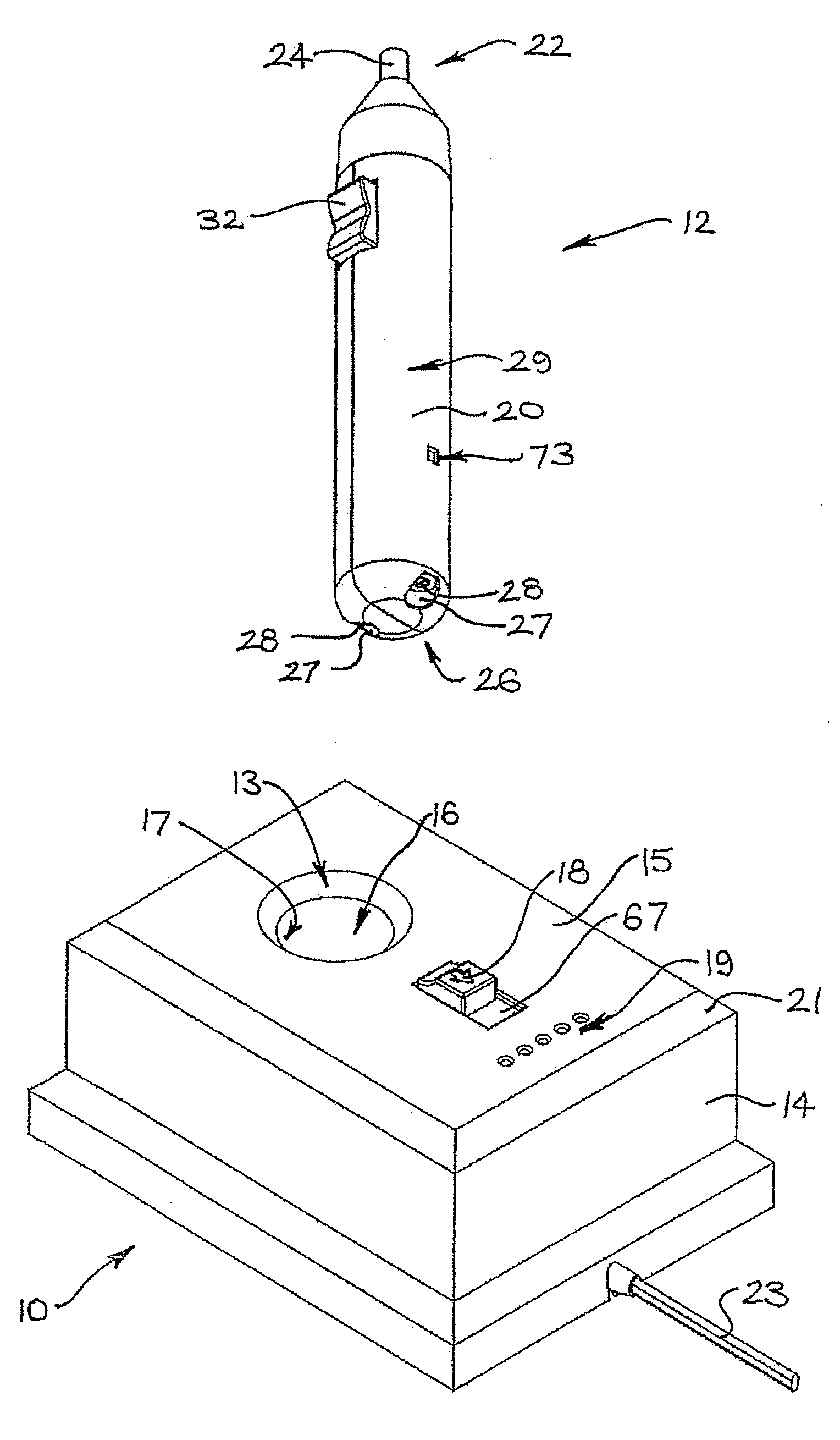
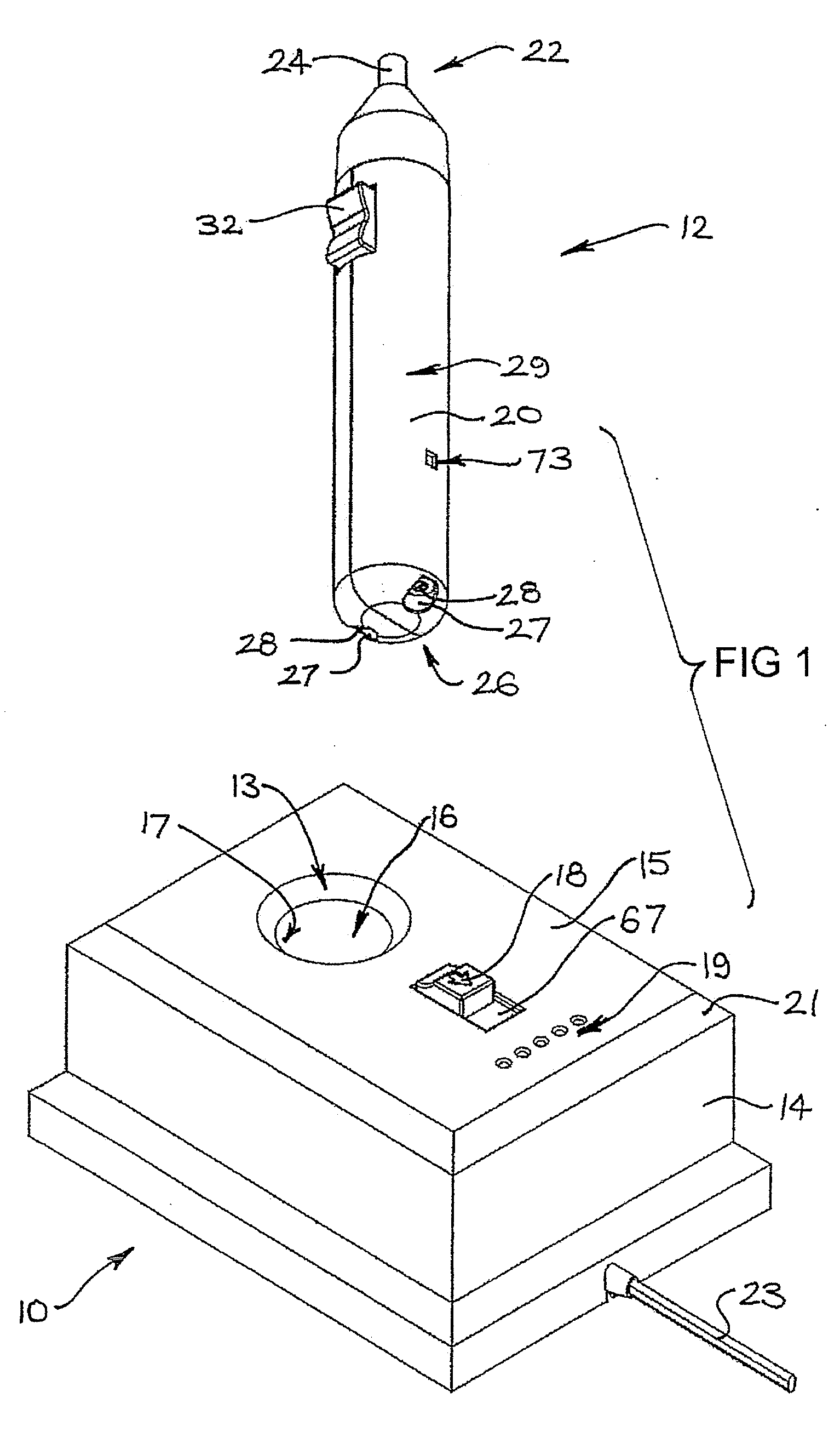
[0088]Referring to FIGS. 1 and 2, there is shown an electrical charger 10 for charging a rechargeable device, in this case a rechargeable electric screwdriver 12. The illustrated charger 10 consists of a generally rectangular box housing 14 having an upper surface 15 (relative to the orientation shown in FIGS. 1 and 2) which includes an opening 13 for a cylindrically shaped support recess 16. The walls 17 of the support recess 16 form a receiver into which the rechargeable electric screwdriver 12 is received for charging as shown in FIG. 2. The upper surface 15 also includes a locking or fastener latch 18, which is longitudinally movable relative to the face of the upper surface 15 of the charger 10.

[0089]In addition, a set of five indicator lights 19, typically LED type lights, are provided on the upper surface 15 between an edge 21 and the fastener latch 18. When the indicator lights 19 are illuminated, they provide an indication of the charging level or capacity of the power stor...


PUM


Abstract

A capacitor-based (supercapacitor, ultracapictor or psudeocapcitor) electrical charger, rechargeable device and energy storage pack for use with a rechargeable power tool. The rechargeable device includes a storage capacitor. The electrical charger includes a supply capacitor electrically connected to an electrical contact, the supply capacitor being charged when the electrical charger is connected to a power source. While in use, any charge in the supply capacitor is rapidly distributed between the supply capacitor and the storage capacitor when the rechargeable device is mounted in the receiver of the electrical charger. The electrical charger includes a safety interlock switch which only supplies power to the electrical contact of the charger after electrical terminal of the rechargeable device have engaged the electrical contact.

Description

CROSS REFERENCE TO RELATED APPLICATIONS[0001]This application is a continuation-in-part application of PCT Application No. PCT / AU2007 / 000536, filed Apr. 26, 2007, which claims priority to AU 2006902155, filed Apr. 26, 2006, both of which are incorporated herein by reference in their entirety.FIELD OF THE INVENTION[0002]The present invention generally relates to rechargeable devices which can be recharged using a charger and / or chargers thereof. In an exemplary application, the invention relates to a rechargeable power tool having a capacitor, including but not limited to a supercapacitor, ultracapacitor or pseudocapacitor, power storage means and a charger thereof and it will be convenient to hereinafter disclose the invention in relation to that exemplary application. However, it is to be appreciated that the invention is not limited to that application.BACKGROUND OF THE INVENTION[0003]The following discussion of the background to the invention is intended to facilitate an understa...

Claims


Application Information

Patent Timeline
Patent Type & Authority Applications(United States)
IPC IPC(8): H02J7/00H01G15/00
CPCH01H13/18H02J7/00H02J7/345H02J7/0044
Inventor VAN DER LINDE, BENJAMIN LUKESCRIMSHAW, DAVID LEIGHDAVIES, PAULMILLER, PAULCONNOR, PAUL FRANCIS
Owner DEMAIN TECH
Why Eureka
Try Eureka