Passive shimming of magnet systems

a magnet system and passive technology, applied in the direction of magnetic resonance measurement, acoustic wave reradiation, measurement devices, etc., can solve the problems of increasing the mass of shim material required to achieve the desired shimming effect, limiting the capacity of each pocket of the shim tray, and limiting the volume of shim material which can be loaded

Inactive Publication Date: 2009-04-16
SIEMENS PLC
View PDF12 Cites 13 Cited by
  • Summary
  • Abstract
  • Description
  • Claims
  • Application Information

AI Technical Summary

Benefits of technology

[0014]The existing shim trays result in a low volume fraction of shimming material in the space set aside in the gradient coil for shimming. This is partly due to the need to provide sufficient space in all pockets for a certain maximum number of shims, and partly due to the need to accommodate the shim tray itself. It has been estimated that in a typically shimmed magnet system, only about 35% of the volume set aside for shimming is in fact occupied by shimming material. The remaining 65% is in effect wasted space. Since designers of such magnet systems seek to optimize use of space, in order to shorten or widen the bore of a hollow cylindrical magnet, such waste of space is desired to be avoided. To minimize the wasted space, the capacity of each pocket of the shim tray may be limited. However, this in turn not only limits the volume of shim material which can be loaded, but also means that the shim pockets near the most sensitive regions, typically towards the centre of the magnet, are filled up quickly, forcing any further required shim material into less sensitive regions and consequently increasing the mass of shim material required to achieve the desired shimming effect.

Problems solved by technology

To minimize the wasted space, the capacity of each pocket of the shim tray may be limited.
However, this in turn not only limits the volume of shim material which can be loaded, but also means that the shim pockets near the most sensitive regions, typically towards the centre of the magnet, are filled up quickly, forcing any further required shim material into less sensitive regions and consequently increasing the mass of shim material required to achieve the desired shimming effect.
This leads to stress concentration at the corners of the slots, which tends to impair the structural integrity of the gradient coil.

Method used


Image

  • Passive shimming of magnet systems
  • Passive shimming of magnet systems
  • Passive shimming of magnet systems

Examples


Embodiment Construction

[0026]According to an aspect of the present invention, shim trays are dispensed with. Furthermore, substantially planar shim pieces are arranged perpendicular to the axis of a hollow cylindrical magnet. Preferably, the shim pieces are planar, and more preferably circular, and the gradient coil assembly is provided with a number of cylindrical shim tubes for accommodating the shim pieces. Preferably, an arrangement is provided for cooling the shim pieces in-situ.

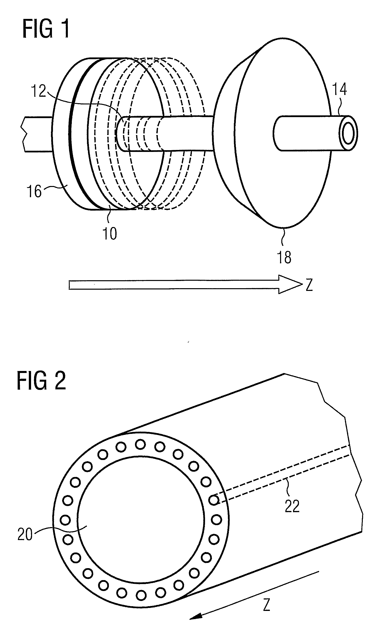
[0027]The geometry of certain embodiments of the present invention, given by way of example only, is shown schematically in FIGS. 1 and 2.

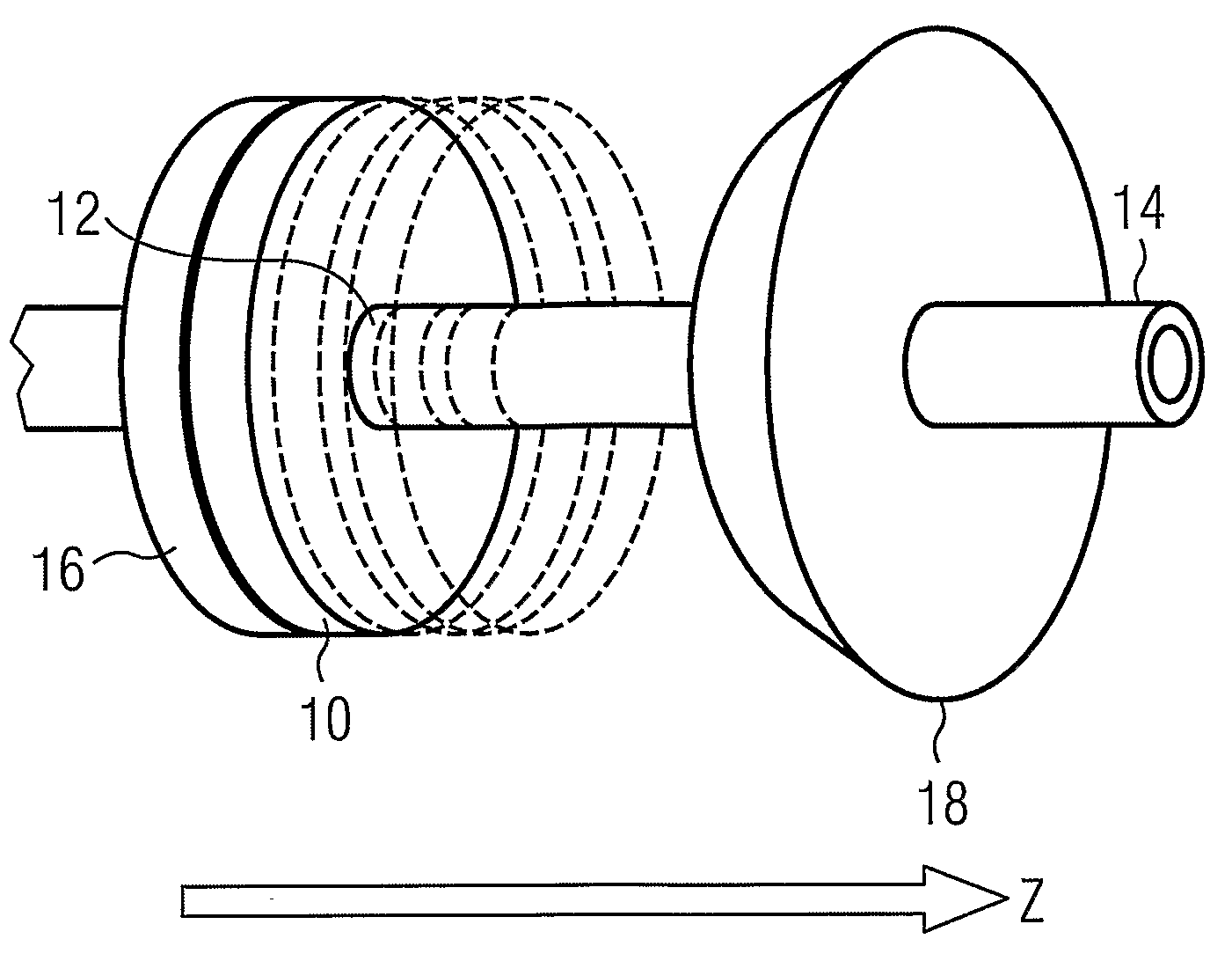
[0028]FIG. 1 shows a detail of a shim arrangement according to an aspect of the present invention. According to this embodiment of the invention, discs 10 of shimming material are arranged within the gradient coil assembly 20 (FIG. 2) in tubes 22 of complementary cross-section, provided for the purpose. In the illustrated embodiment, the discs 10 are circular, and the tubes 22 have a circul...


PUM


Abstract

In a method and an arrangement for shimming a cylindrical magnet system, that has a cylindrical magnet having a bore therein with an axis extending therethrough, and a gradient coil assembly located within the bore, shimming is accomplished by stacking a number of planar pieces of shim material in each of said tubes, with each of the tubes having an axis parallel to the axis of the cylindrical magnet, and with the planar pieces of shim material and stacked in the tubes in respective planes that are perpendicular to the axis fo the cylindrical magnet.

Description

BACKGROUND OF THE INVENTION[0001]1. Field of the Invention[0002]The present invention relates to shimming of magnet systems, and in particular to passive shimming of magnet systems.[0003]2. Description of the Prior Art[0004]Applications such as magnetic resonance imaging (MRI) or nuclear magnetic resonance (NMR) imaging require magnetic fields of high strength and very high homogeneity. Such magnetic fields are commonly provided by electromagnets comprising a number of superconducting or resistive coils arranged in a fixed arrangement.[0005]As is well known in the art, considerable effort goes into the design of magnet systems to enable them to produce high strength homogeneous fields. However, it is not possible to design a magnet which will produce its designed homogeneity in a real application. Manufacturing tolerances inevitably displace the coils from their design position, and characteristics of the wire used may be different from those assumed in the design process. Furthermo...

Claims


Application Information

Patent Timeline
Patent Type & Authority Applications(United States)
IPC IPC(8): G01R33/38
CPCG01R33/3873
Inventor BARNES, TIMOTHYCATMULL, BENJAMIN JOHNTOYER, JOHN HEDLEYWILKINSON, IAN
Owner SIEMENS PLC
Why Eureka
Try Eureka