Scroll wheel device

a technology of scroll wheel and scroll wheel, which is applied in the direction of instruments, computing, electric digital data processing, etc., can solve the problems of limiting the operation life of the switch encoder, limited scrolling resolution, and inability to provide continuous scrolling, so as to achieve smooth scrolling of the onscreen image and greater scrolling resolution

Inactive Publication Date: 2009-04-16
SUNREX TECH +1
View PDF4 Cites 13 Cited by
  • Summary
  • Abstract
  • Description
  • Claims
  • Application Information

AI Technical Summary

Benefits of technology

[0007]Compared to conventional mechanical or optical means, the present invention provides a number of advantages. First of all, the scroll wheel device is able to provide analog or continuous electrical signals and therefore is able to achieve significantly greater scrolling resolution and smooth scrolling of the onscreen image. Secondly, the scrolling resolution is not related to the diameter of the wheel module and therefore the scroll wheel device may be integrated into miniature electronic devices.

Problems solved by technology

First, as a mechanical means, the switch encoder may suffer deteriorated contact after a period of usage, thereby limiting its operation life.
Secondly, with its inherent limitation, the switch encoder has a limited scrolling resolution and cannot provide continuous scrolling.
Even though some computer mice adopt optical encoders to obviate some of the shortcomings of the mechanical switch encoder, the optical encoder still suffers some disadvantages.
To achieve high scrolling resolution, a bigger scroll wheel has to be adopted and the optical encoder is therefore not appropriate for a miniature pointing device.
If a smaller scroll wheel is used, the scrolling resolution again is limited.

Method used


Image

  • Scroll wheel device
  • Scroll wheel device
  • Scroll wheel device

Examples


Embodiment Construction

[0016]The following descriptions are exemplary embodiments only, and are not intended to limit the scope, applicability or configuration of the invention in any way. Rather, the following description provides a convenient illustration for implementing exemplary embodiments of the invention. Various changes to the described embodiments may be made in the function and arrangement of the elements described without departing from the scope of the invention as set forth in the appended claims.

[0017]In the following, a computer mouse is mainly used as an example to explain the embodiment of the present invention. However, the principle of the present invention may be readily applied to various types of other pointing or electronic devices.

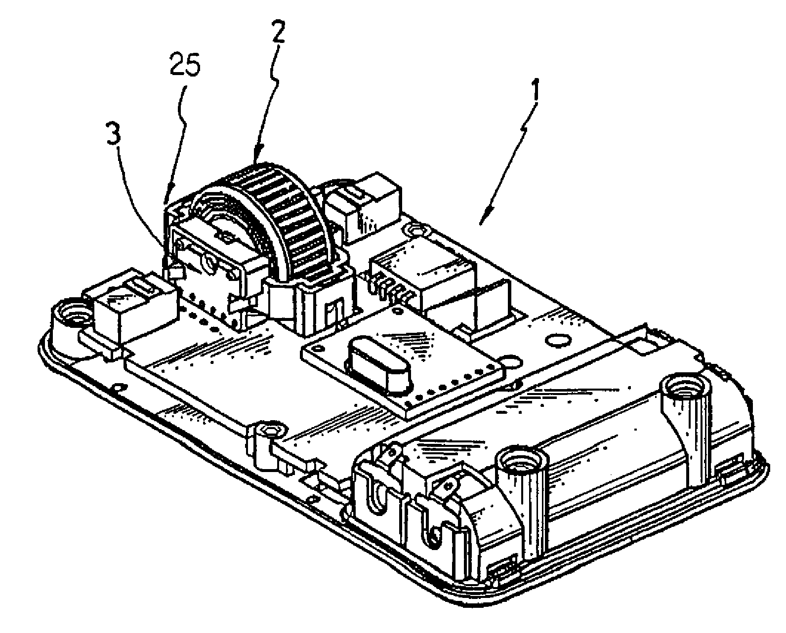
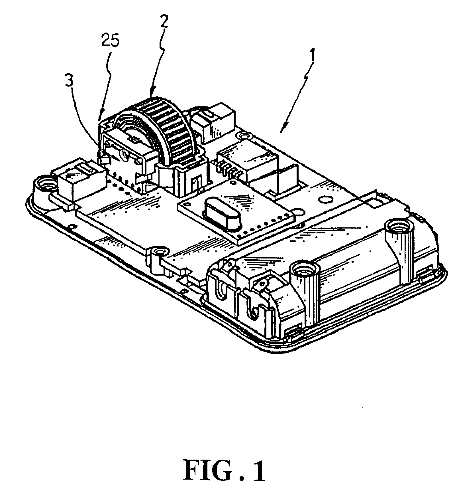
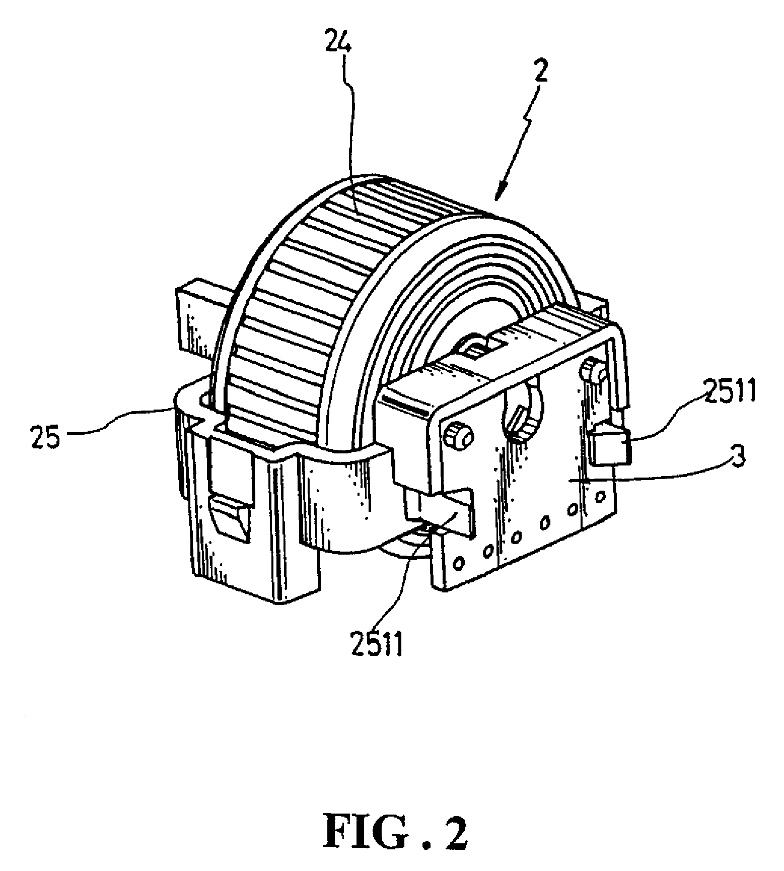
[0018]FIG. 1 shows an embodiment of the present invention housed inside a computer mouse 1, with a top cover of the computer mouse 1 removed to reveal the details inside. As further illustrated in FIG. 2, the present embodiment contains a wheel module 2 ...


PUM


Abstract

The major characteristic of the present invention lies in the adoption of electromagnetic means to translate the spin of a wheel module into continuous electrical signals. A permanent magnet is incorporated in the wheel module to provide magnetic field. Two sensors tangential to the spinning direction of the permanent magnet are used to detect the variations of the magnetic field from the spin of the wheel module in accordance with the Hall Effect.

Description

TECHNICAL FIELD OF THE INVENTION[0001]The present invention generally relates to pointing devices, and more particularly to a scroll wheel device for use in a pointing device to translate the spin of a wheel module into corresponding electrical signals.DESCRIPTION OF THE PRIOR ART[0002]In addition to the conventional pointing and clicking functions, a recent innovation in computer mice is to integrate a scroll wheel that allows a user to scroll the onscreen image of a document like a Web page or spreadsheet vertically (up / down) and / or horizontally.[0003]Usually a mechanical switch encoder is adopted to translate the spin of the scroll wheel into signals that a computer can use. The mechanical switch encoder has a number of disadvantages. First, as a mechanical means, the switch encoder may suffer deteriorated contact after a period of usage, thereby limiting its operation life. Secondly, with its inherent limitation, the switch encoder has a limited scrolling resolution and cannot p...

Claims


Application Information

Patent Timeline
Patent Type & Authority Applications(United States)
IPC IPC(8): G06F3/033
CPCG06F3/0362G06F3/03543
Inventor LEE, WEN-CHIN
Owner SUNREX TECH
Why Eureka
Try Eureka