
Fuse latch circuit and fuse latch method

a latch circuit and fuse technology, applied in the direction of read-only memories, instruments, static storage, etc., can solve problems such as unstable internal circuits, and achieve the effects of detecting and latching the state of fuse elements stably, sufficient time margin, and reliable

Inactive Publication Date: 2009-04-16
PS4 LUXCO SARL
View PDF9 Cites 4 Cited by
  • Summary
  • Abstract
  • Description
  • Claims
  • Application Information

AI Technical Summary

Benefits of technology

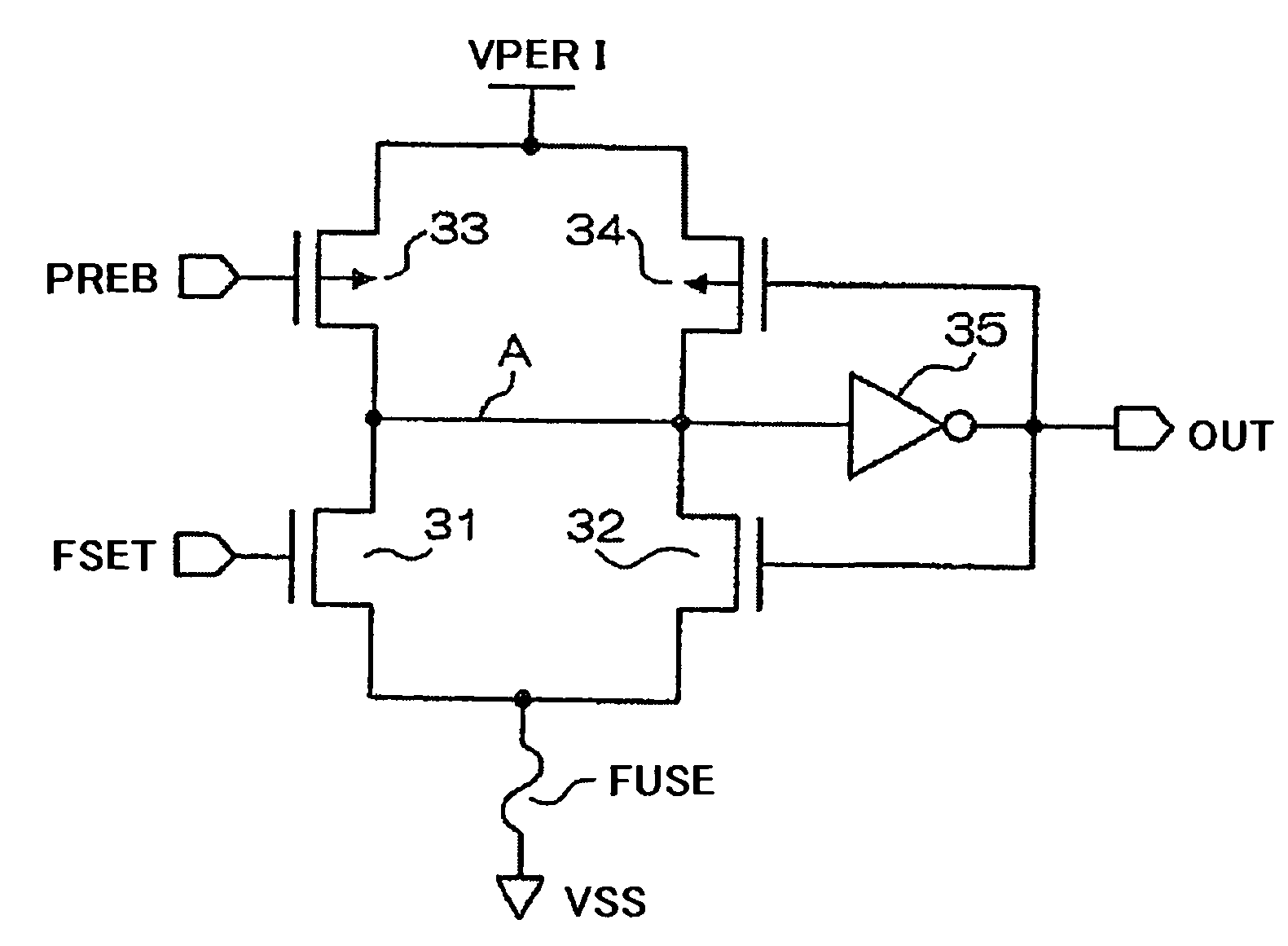
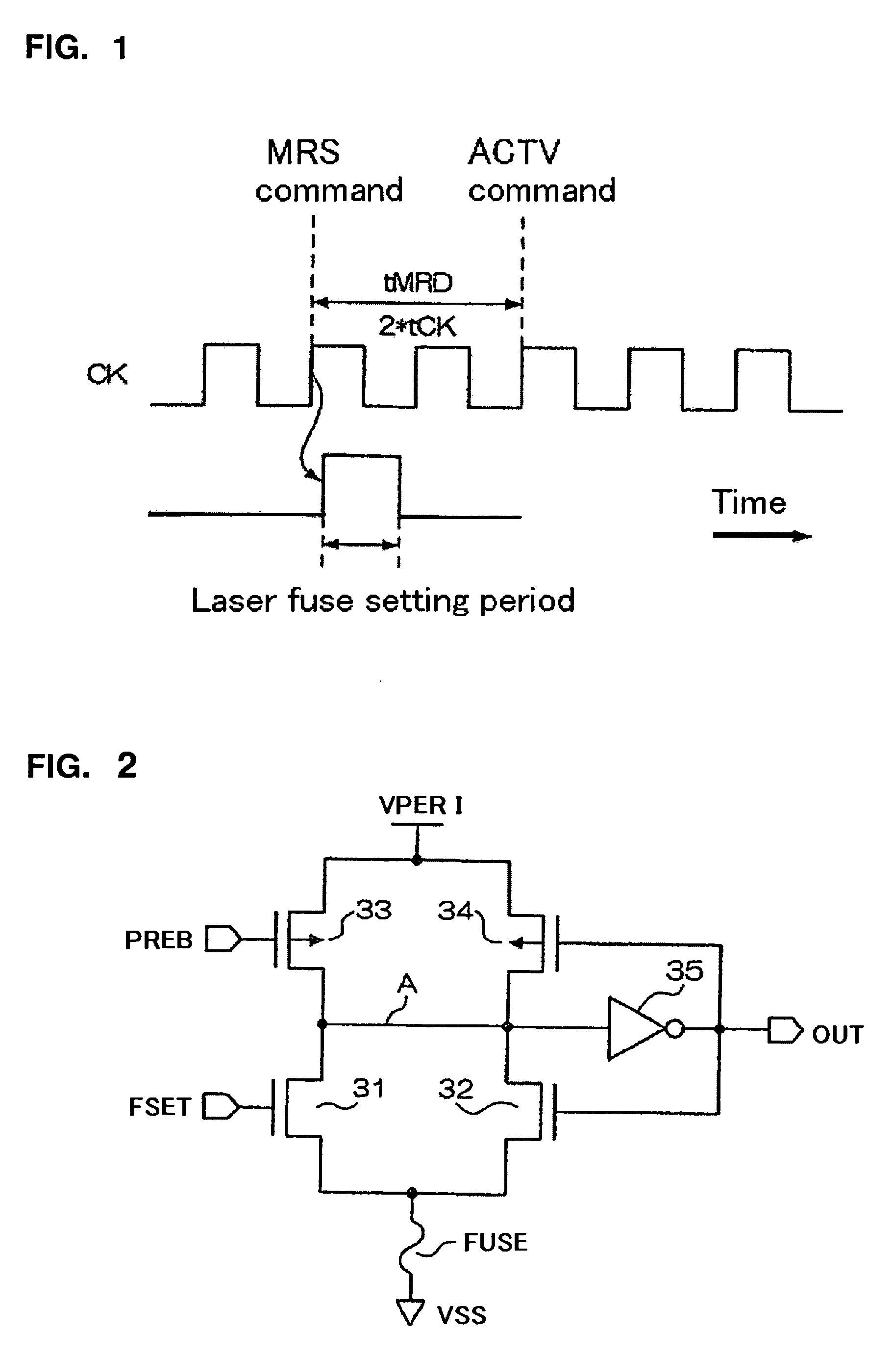
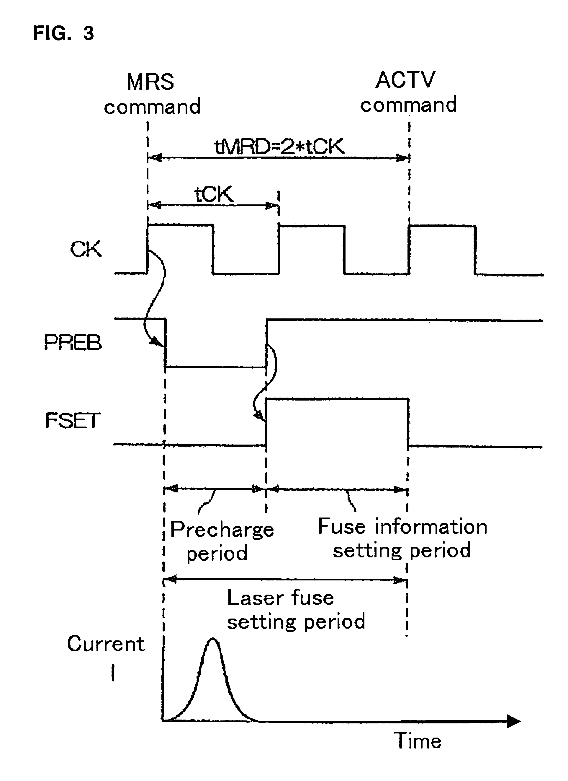
[0014]As described above with reference to FIGS. 2 and 3, a period of several nanoseconds is required to set the fuse information. On the other hand, in the case of a conventional LPDDR (266@tCK=7.5 ns) memory as shown in FIG. 4A, the data transfer rate is about 266 Mbps, and hence the clock cycle tCK is as low as 7.5 ns. Therefore, it is possible to set the fuse information within the period of tMRD=2*tCK=15 ns. The LPDDR memory thus provides leeway in terms of timing as indicated by a circle in FIG. 4A.
[0021]According to the present invention, a fuse latch circuit is started by using, as a trigger, a command such as a MRS reset command to reset an operation mode register after power-on. Fuse information can be latched in a period of time from input of a MRS reset command until input of a MRS command which is a command to set an operation mode in the operation mode register. The duration of time from the input of the MRS reset command to the input of the MRS command is determined to be for example about 1 μs. Thus, a sufficient time margin can be ensured for a conventional laser fuse setting period. This makes it possible to detect and latch the state of a fuse element stably and reliably.

Problems solved by technology

An internal circuit is unstable particularly during generation of the power-on signal.

Method used


Image

  • Fuse latch circuit and fuse latch method
  • Fuse latch circuit and fuse latch method
  • Fuse latch circuit and fuse latch method

Examples


Embodiment Construction

[0033]An exemplary embodiment of a fuse latch circuit according to this invention will be described with reference to the accompanying drawings. The fuse latch circuit of this embodiment can be provided, for example, in a LSI (large-scale integrated circuit) which has a large number of fuse elements and implements various functions, including resetting of an operation mode register by using a MRS reset command. The LSI may for example be a LPDDR2-DRAM (LPDDR2 dynamic random access memory).

[0034]In the first place, characteristics of the embodiment will be described with reference to FIG. 5. The shown embodiment is characterized by how a fuse latch circuit is activated. In other words, it is characterized in that the fuse latch circuit is activated with the use of a MRS reset command. This MRS reset command (mode register set reset command) is a command for resetting a MRS (mode register set) and is to be employed in LPDDR2, for example. Specifically, a principal characteristics of t...


PUM


Abstract

A fuse latch circuit starts a precharge operation for reading out a state of a fuse element when receiving an external command which is a command to reset an operation mode register (MRS reset command) after power-on, and reads out and latches the state of the fuse element after completion of the precharge operation.

Description

[0001]This application is based upon and claims the benefit of priority from Japanese Patent Application No. 2007-266453, filed Oct. 12, 2007, the disclosure of which is incorporated herein in its entirety by reference.BACKGROUND OF THE INVENTION[0002]1. Field of the Invention[0003]This invention relates to a fuse latch circuit and a fuse latch method for detecting a state of a fuse element in a semiconductor device.[0004]2. Description of the Related Art[0005]A semiconductor device typically uses a fuse element to store information specific to the semiconductor device in the semiconductor device. Japanese Laid-Open Patent Publication No. 2004-246958, for example, describes a semiconductor device which is designed to detect a state of a fuse element reliably by reading out the state of the fuse element based on a reset signal instructing a first reset operation after power-on.SUMMARY OF THE INVENTION[0006]Referring to FIG. 1 and FIG. 2, problems to be solved by this invention will b...

Claims


Application Information

Patent Timeline
Patent Type & Authority Applications(United States)
IPC IPC(8): G11C7/00G11C11/21
CPCG11C7/1045G11C17/18G11C17/14
Inventor YOKO, HIDEYUKI
Owner PS4 LUXCO SARL
Learn More