

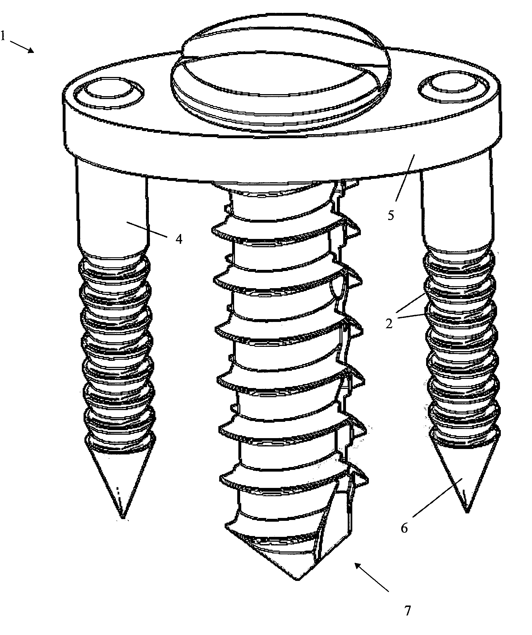
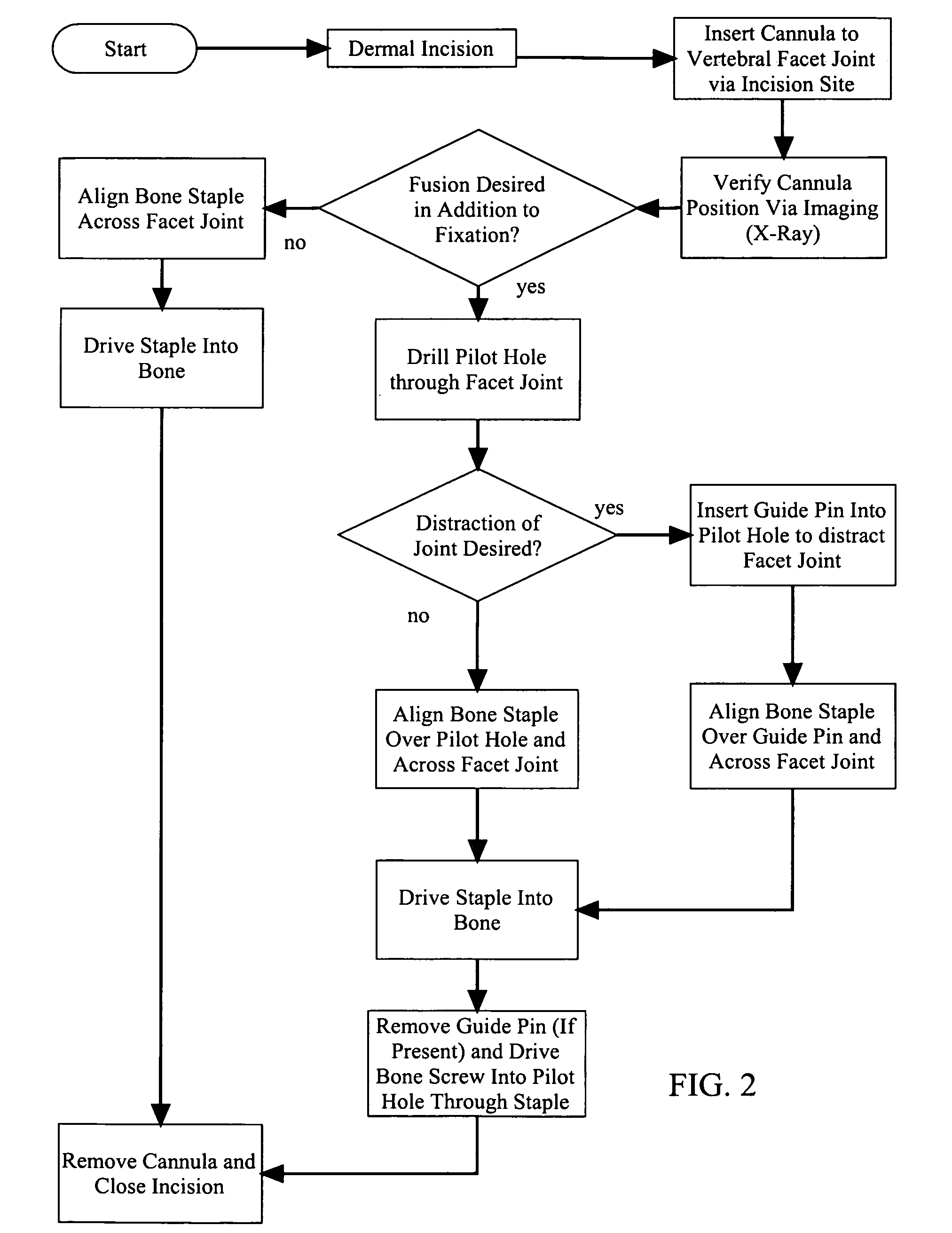
Method of lateral facet approach, decompression and fusion using screws and staples as well as arthroplasty
- Summary
- Abstract
- Description
- Claims
- Application Information
AI Technical Summary
Benefits of technology
Problems solved by technology
Method used
Image

Examples
Embodiment Construction
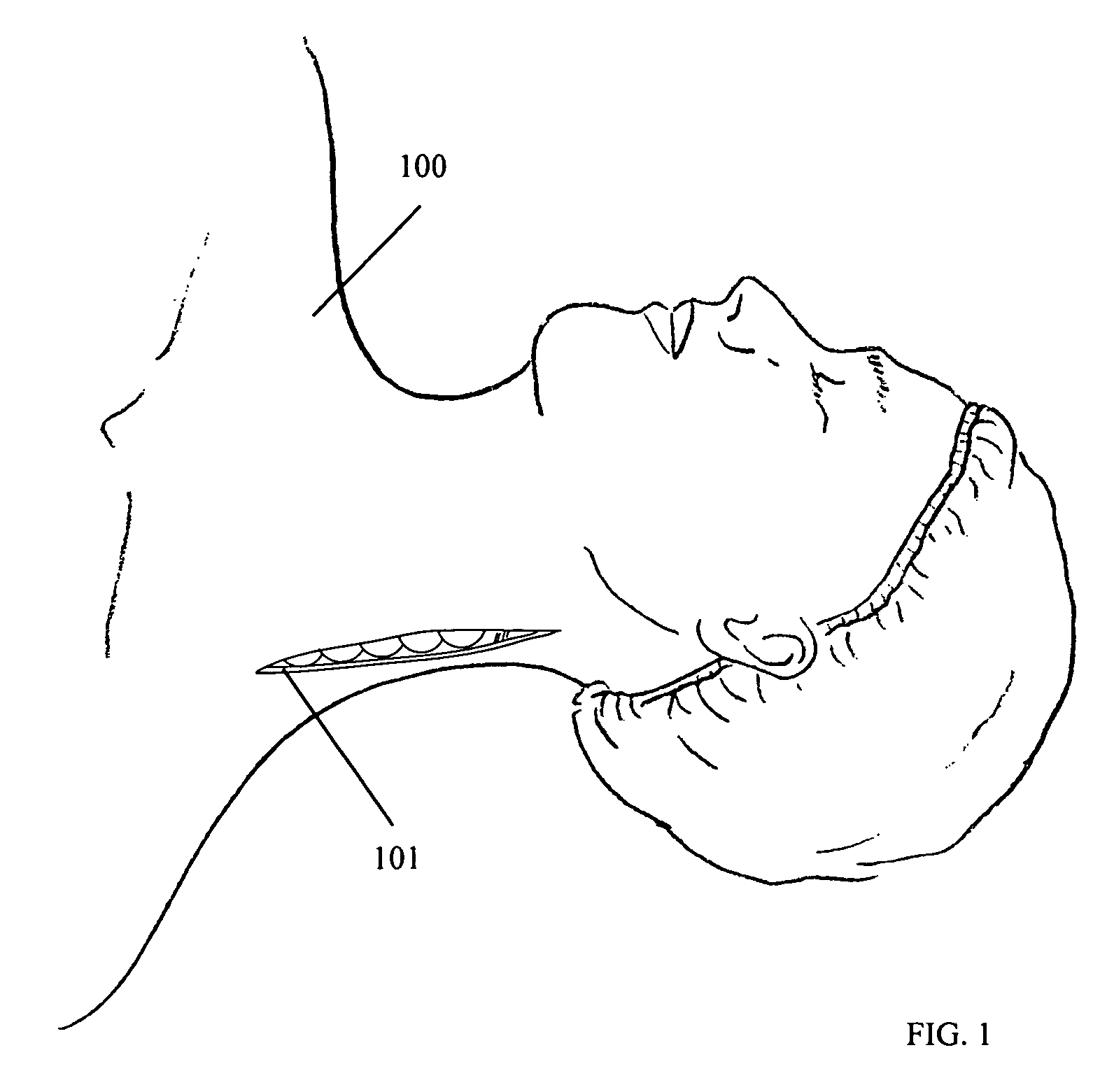
[0030]The present invention provides for a minimally invasive surgical implantation method and apparatus for cervical spine implants that preserves the structure and to a limited degree the function of the spine. In addition to stabilization, embodiments of the invention provide for distracting the cervical vertebra to increase the foraminal space and relieve pain by reducing pressure on the neural structures and blood vessels of the cervical spine.
[0031]Two facet joints are formed between each vertebrae of the spine. Each vertebra has two superior articulating facets and two inferior articulating facets, with the superior facet of a lower vertebra and an inferior facet of an upper vertebra meeting and aligning to form one facet joint on each side of the spine. In the cervical spine, the upward inclination of the superior articular surfaces of the facet joints allows for considerable flexion and extension, as well as for lateral mobility. Each facet joint is covered by a dense, elas...
PUM
 Abstract
Description
Claims
Application Information