Design structure for partitioned dummy fill shapes for reduced mask bias with alternating phase shift masks

a mask and phase shift technology, applied in the field of partitioned dummy fill shapes for reducing mask bias with alternating phase shift masks, can solve the problems of adverse effects on the dimensional control of features, adverse effects on the manufacturing mask bias of both phase and block reticles, and adverse effects on masks used in other two-mask lithographic processes incorporating an auxiliary trim mask

Inactive Publication Date: 2009-04-16
GLOBALFOUNDRIES INC
View PDF16 Cites 2 Cited by
  • Summary
  • Abstract
  • Description
  • Claims
  • Application Information

AI Technical Summary

Benefits of technology

[0007]In a first aspect of the invention, a method comprises locating regions in a finished semiconductor design that do not contain as-designed shapes. The method generates dummy fill shapes in the regions at a predetermined final density and sizes the generated dummy shapes so that their local density is increased to a predetermined value. The method further creates corresponding trim shapes that act to expose an oversized portion of the dummy shape, effectively trimming each dummy shape back to the predetermined final density.

Problems solved by technology

Variations in the local density of shapes are known to have an adverse effect on the dimensional control of features on those masks, and these non-uniformities have been demonstrated to exhibit a strong adverse effect on the manufacturing mask bias for both phase and block reticles.
Similar manufacturing difficulties arising from non-uniform density of shapes can adversely affect masks used in other two-mask lithographic processes incorporating an auxiliary trim mask, used for example to create closely-space line ends in an SRAM or other memory array.
This approach increases the cost and turnaround-time for the masks, has the potential to increase the defect density on those masks, and is inherently a one-way process only.
That is, features that were rendered too large can be trimmed, but features that were originally rendered too small cannot be readily adjusted.

Method used


Image

  • Design structure for partitioned dummy fill shapes for reduced mask bias with alternating phase shift masks
  • Design structure for partitioned dummy fill shapes for reduced mask bias with alternating phase shift masks
  • Design structure for partitioned dummy fill shapes for reduced mask bias with alternating phase shift masks

Examples


Embodiment Construction

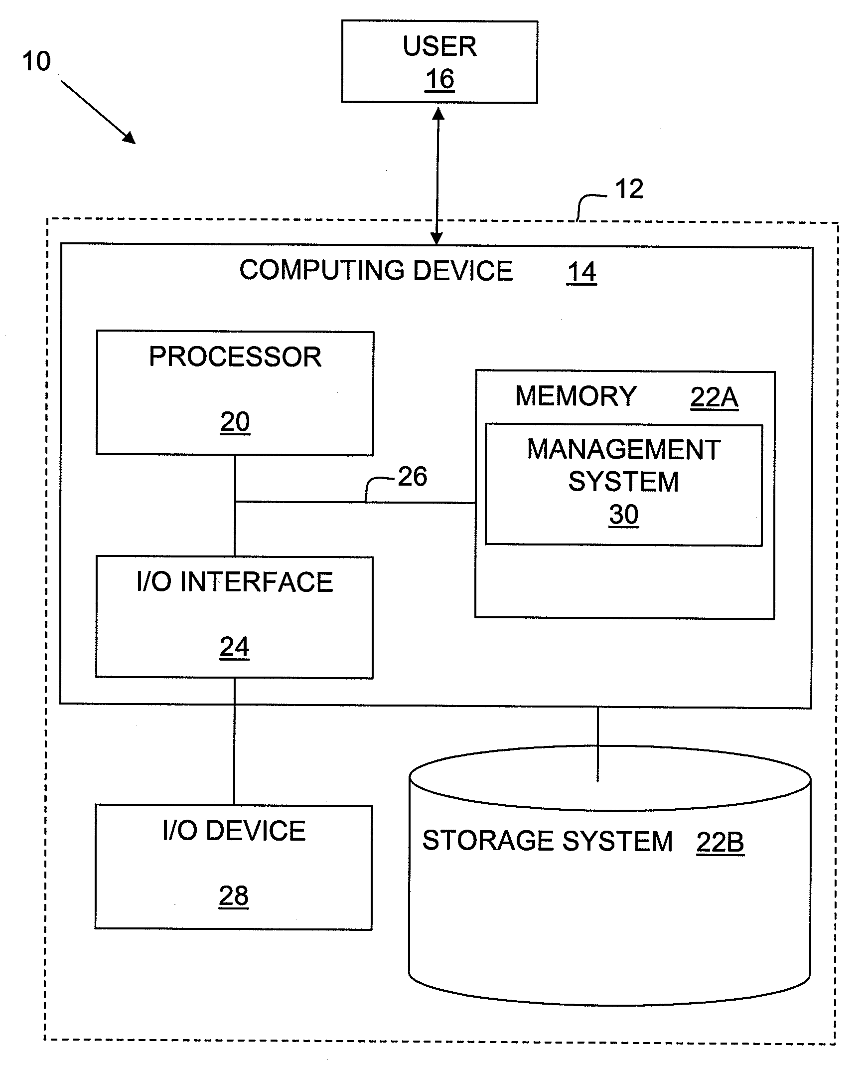
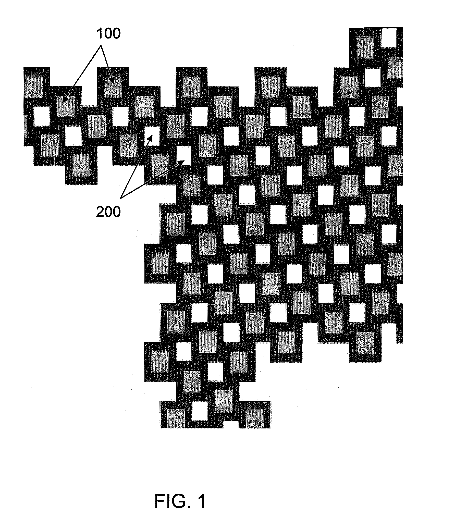
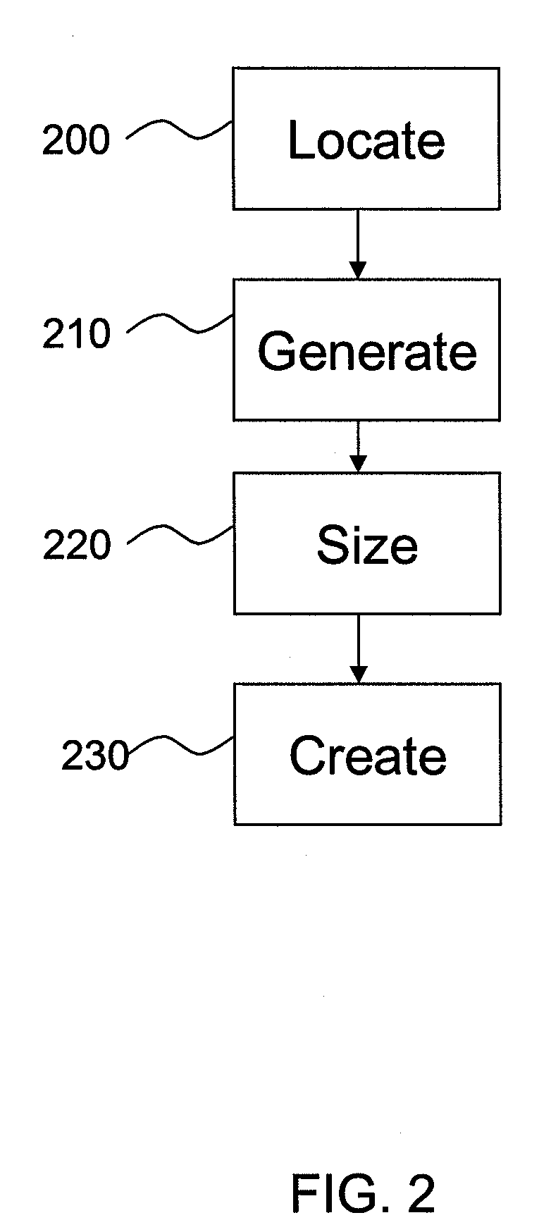
[0022]The invention relates to a method and system for partitioned dummy fill shapes for reduced mask bias with alternating phase shift masks or other two-mask lithographic processes incorporating a trim mask. The invention further relates to a design structure on which a subject circuit resides. In an embodiment of the invention, mask patterns that are rendered as dummy fill shapes are partitioned across two masks, e.g., on a phase mask and a block mask, such that the local density of shapes on both masks can be made significantly more uniform. Specifically, in embodiments, the shapes on the block mask associated with dummy fill are expanded until their local density is in the desired range (e.g., typically 70-90%), and associated trim shapes on the phase mask are used to trim the oversized (expanded) block shapes to their desired size. In this manner, regions containing dummy fill shapes, such as spaces between dense circuit macros, and companion chiplets on a technology developme...


PUM


Abstract

A design structure, method, and system for partitioned dummy fill shapes for reduced mask bias with alternating phase shift masks, or with other two-mask lithographic processes employing a trim mask. A design structure is embodied in a machine readable medium used in a design process, the design structure comprising regions in a finished semiconductor design that do not contain as-designed shapes. The design structure additionally includes dummy fill shapes in the regions at a predetermined final density, wherein the generated dummy shapes are sized so that their local density is increased to a predetermined value. Moreover, corresponding trim shapes act to expose an oversized portion of the dummy shape, effectively trimming each dummy shape back to the predetermined final density.

Description

CROSS-REFERENCE TO RELATED APPLICATIONS[0001]The present application is a continuation in part of U.S. application Ser. No. 11 / 539,204 filed on Oct. 6, 2006, the disclosure of which is expressly incorporated by reference herein in its entirety.DESCRIPTIONField of the Invention[0002]The invention relates to a method and system for partitioned dummy fill shapes for reduced mask bias with alternating phase shift masks, or with other two-mask lithographic processes employing a trim mask. The invention further relates to a design structure on which a subject circuit resides.BACKGROUND DESCRIPTION[0003]Phase shift mask technology allows for much smaller features to be resolved for a given illumination wavelength than conventional Chrome-On-Glass or Attenuated Phase Shift methods. Typically small features are resolved by exposing the spaces on either side through alternating 0-degree and 180-degree phase-shifted openings on a phase mask. The ends of these fine features are normally trimmed...

Claims


Application Information

Patent Timeline
Patent Type & Authority Applications(United States)
IPC IPC(8): G06F17/50
CPCG06F2217/12G06F17/5068G06F30/39G06F2119/18Y02P90/02
Inventor FAURE, THOMAS B.LANDIS, HOWARD S.SUCHARITAVES, JEANNE-TANIA
Owner GLOBALFOUNDRIES INC
Why Eureka
Try Eureka