
NFC reader having a passive operating mode with low electrical consumption

a passive operating mode and nfc reader technology, applied in the field of inductive coupling methods of data transmission, can solve the problems of non-negligible current consumption of nfc readers, embodiment does not solve the problem of electrical overconsumption, and the purpose is more difficult to achieve with a nfc reader equipped with a removable security module than with a simple contactless chip card. achieve the effect of low electrical consumption

Inactive Publication Date: 2009-04-23
STMICROELECTRONICS SRL
View PDF10 Cites 64 Cited by
  • Summary
  • Abstract
  • Description
  • Claims
  • Application Information

AI Technical Summary

Benefits of technology

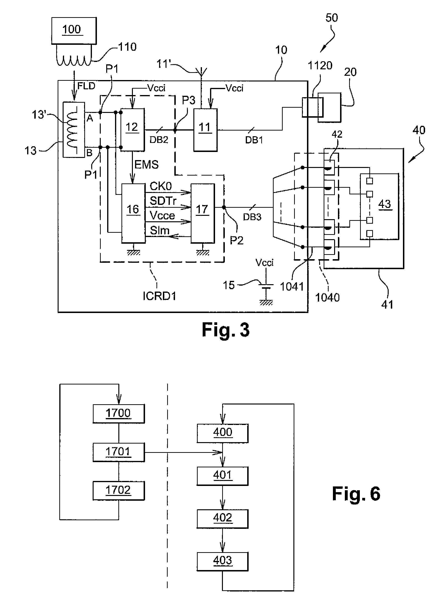
[0025]One embodiment provides an architecture of a NFC reader having a low electrical consumption in the emulation mode.
[0026]Another embodiment provides a NFC reader able to operate autonomously in emulation mode while offering a satisfactory communication distance.

Problems solved by technology

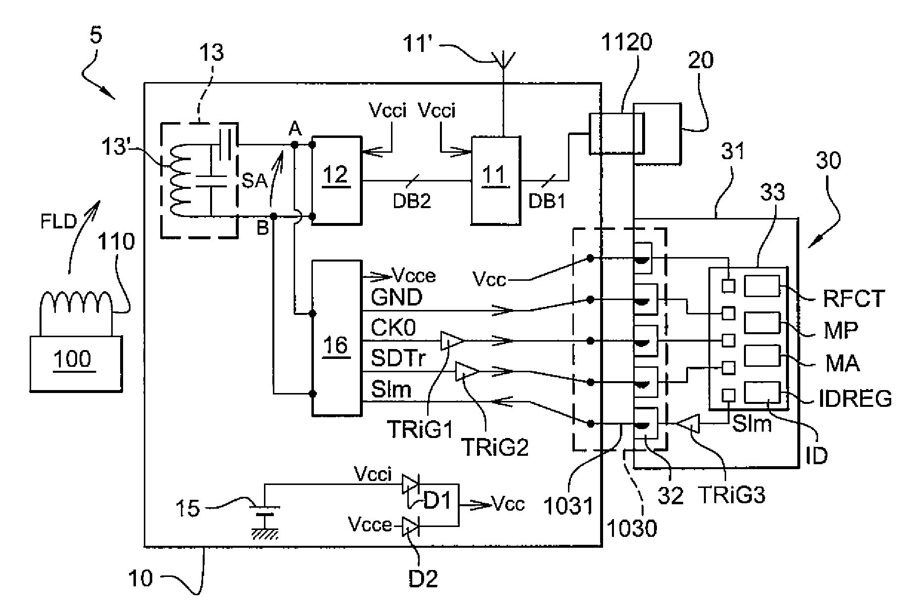
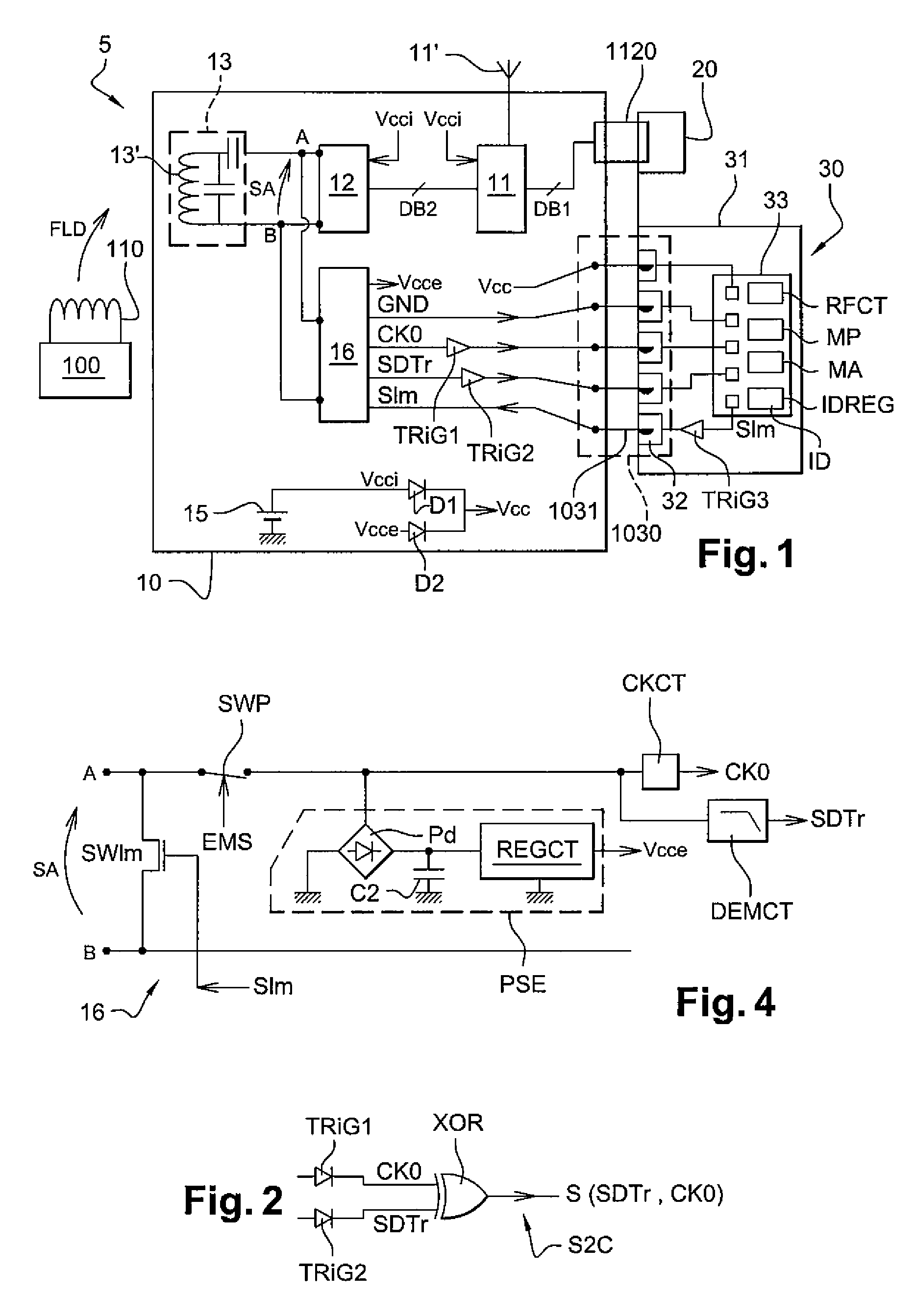
However, this purpose is more difficult to achieve with a NFC reader equipped with a removable security module than with a simple contactless chip card, for some reasons that will be understood by referring to FIG. 1.
However, this NFC reader consumes a non-negligible current, generally about a few milliamperes.
However, this embodiment does not solve the problem of electrical overconsumption, the voltage Vcce and the current supplied by the passive interface circuit 16 further having to electrically power the XOR gate.
In addition, the electrical consumption of the circuit TRIG1 is high because the circuit switches at a high frequency, that is 13.56 MHz.

Method used


Image

  • NFC reader having a passive operating mode with low electrical consumption
  • NFC reader having a passive operating mode with low electrical consumption
  • NFC reader having a passive operating mode with low electrical consumption

Examples


Embodiment Construction

[0069]In the following description, numerous specific details are given to provide a thorough understanding of embodiments. The embodiments can be practiced without one or more of the specific details, or with other methods, components, materials, etc. In other instances, well-known structures, materials, or operations are not shown or described in detail to avoid obscuring aspects of the embodiments.

[0070]Reference throughout this specification to “one embodiment” or “an embodiment” means that a particular feature, structure, or characteristic described in connection with the embodiment is included in at least one embodiment. Thus, the appearances of the phrases “in one embodiment” or “in an embodiment” in various places throughout this specification are not necessarily all referring to the same embodiment. Furthermore, the particular features, structures, or characteristics may be combined in any suitable manner in one or more embodiments.

[0071]The headings provided herein are for...


PUM


Abstract

An inductive coupling reader includes a passive interface circuit for modulating the impedance of an antenna circuit and extracting from the antenna circuit a data signal and a RF clock signal, and circuitry for coupling the reader to a removable security module. The reader includes an emulation circuit for opening a RF transmission channel with another reader, a non-removable electrical link linking the emulation circuit to the passive interface circuit, by which the data signal and the RF clock signal are supplied to the emulation circuit, and a data bus clocked by a bus clock signal having a frequency inferior to the frequency of the RF clock signal, for linking the emulation circuit to the removable security module. The reader has low electrical consumption.

Description

TECHNICAL FIELD[0001]The present disclosure generally relates to methods of data transmission by inductive coupling, and more particularly but not exclusively contactless integrated circuits readers operating by inductive coupling. These readers have various designations, such as “PCD” (Proximity Coupling Device), “VCD” (Vicinity Coupling Device), “inductive couplers” . . . .BACKGROUND INFORMATION[0002]The methods of data transmission by inductive coupling were originally developed for RFID (Radio Frequency Identification) applications, in order to read contactless electronic tags (products identification) or contactless badges (people identification). Because of the technological advances of these last years, these methods are now easily implemented and are considered as forming an outright technique of data transmission, which is not only reserved for identification applications but can also be used to create a RF transmission channel between two devices to make various kinds of p...

Claims


Application Information

Patent Timeline
Patent Type & Authority Applications(United States)
IPC IPC(8): G06K7/06
CPCG06K7/0008H04B5/0056G06K19/0723H04B5/77
Inventor MANI, CHRISTOPHEDELL'OVA, FRANCISRIZZO, PIERRE
Owner STMICROELECTRONICS SRL
Learn More