Discharge controller

a discharge controller and discharge voltage technology, applied in the direction of battery/fuel cell control arrangement, instruments, electrochemical generators, etc., can solve the problem of prolonging the time required for the equalization of the cell voltage of the cell

Active Publication Date: 2009-04-23
HONDA MOTOR CO LTD
View PDF11 Cites 49 Cited by
  • Summary
  • Abstract
  • Description
  • Claims
  • Application Information

AI Technical Summary

Benefits of technology

[0037]Also, according to the present invention, an electric power can be supplied stably to the rotary inductive load such that the power feed is not so affected by variation in level of the discharge voltage of the storage cell.

Problems solved by technology

However, when the discharge current is small, a time required for the equalization of the cell voltages of the cells is prolonged.

Method used


Image

  • Discharge controller
  • Discharge controller
  • Discharge controller

Examples


first embodiment

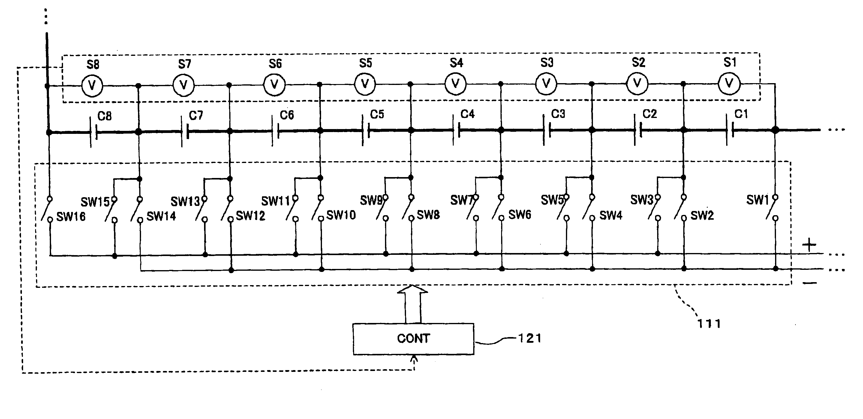
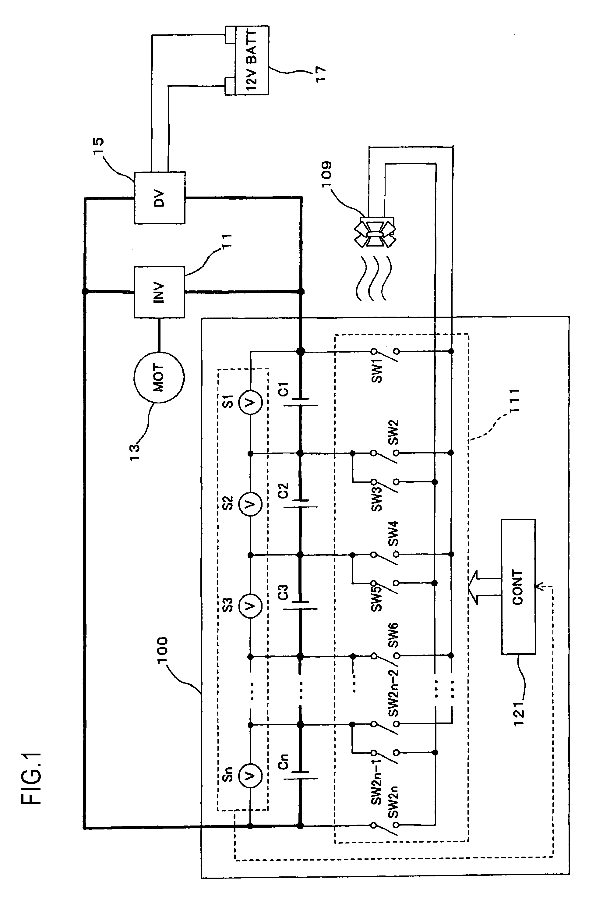
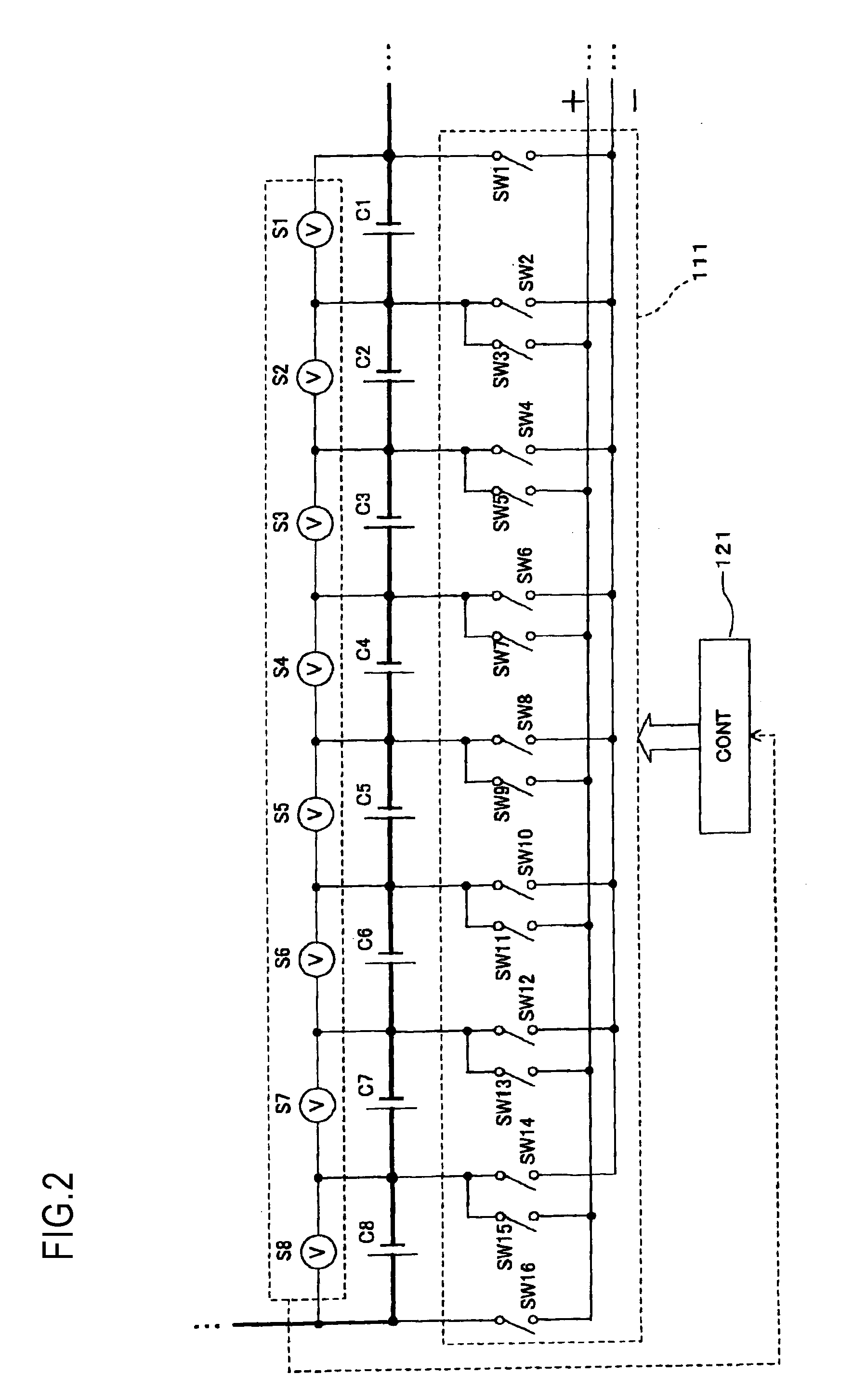
[0065]FIG. 1 is a block diagram showing a relationship between a multiple cell battery of a first embodiment installed in a vehicle, a part of an electric drive system, and accessories. The vehicle shown in FIG. 1 is equipped with a multiple cell battery 100 of the first embodiment, the inverter 11, the motor 13, the DC-DC converter 15, the battery 17, and an electric motor 109 for a cooling fan as a rotary inductive load (referred to as an “electric motor” hereinafter). The inverter 11, the motor 13, the DC-DC converter 15, and the battery 17 are the same as the constituent elements shown FIG. 23.

[0066]An output voltage of the multiple cell battery 100 of the first embodiment is a high voltage (e.g., 100 to 200 V), and an output voltage of the battery 17 is a voltage for the accessories (e.g., low voltage of 12V). The output voltage of the multiple cell battery 100 is converted from DC to AC by the inverter 11, and then is fed to the motor 13. Also, the output voltage of the multip...

second embodiment

[0107]In the first embodiment, the discharge path is formed from at least one cell of the series-connected cells to the electric motor 109 for the cooling fan as the rotary inductive load, by the ON / OFF-control of the switches SW1 to SW2n of the control unit 121. In a second embodiment, the discharge path is formed from one cell whose cell voltage is highest among the cells installed into the multiple cell battery 100 to the electric motor 109. A relationship between the multiple cell battery, a part of the electric drive system, and the accessories in the second embodiment is substantially similar to that shown in FIG. 1 in the first embodiment. But the control unit provided to the multiple cell battery in the second embodiment performs the ON / OFF-control of the switches SW1 to SW2n, which is different from the control unit 121 in the first embodiment.

[0108]The discharge control performed by the control unit in the second embodiment will be described with FIG. 15 and FIGS. 16A to 1...

third embodiment

[0114]A third embodiment is common to the second embodiment in that the discharge path is formed from one cell whose cell voltage is highest among the cells installed into the multiple cell battery 100 to the electric motor 109. But the timing at which the discharge path is switched is different from that in the second embodiment. In other words, in the second embodiment, the discharge is carried out until the cell voltage of the cell from which an electric power is discharged becomes equal to the cell voltage of the cell whose cell voltage is lowest in the multiple cell battery. In contrast, in the third embodiment, the discharge is carried out until the cell voltage of the cell from which an electric power is discharged becomes equal to a voltage that is obtained by subtracting a given voltage from the cell voltage of the cell whose cell voltage is second highest in the multiple cell battery.

[0115]A relationship between the multiple cell battery, a part of the electric drive syste...


PUM


Abstract

There is provided a discharge controller for a multiple cell battery that has a plurality of storage cells connected in series with each other. A discharge path from the storage cell is connected a load. The discharge controller includes: cell voltage detection units for detecting respective cell voltages of the storage cells; a switch group comprising a plurality of switches each connected between the storage cells; and a control unit for performing ON/OFF control on the respective switches individually in response to detection results detected by the cell voltage detection units so as to form the discharge path from the storage cell to the load.

Description

[0001]This application claims priority from Japanese Patent Application No. 2007-275171 filed on Oct. 23, 2007, the entire contents of which are hereby incorporated by reference.BACKGROUND OF THE INVENTION[0002]1. Technical Field[0003]The present disclosure relates to a discharge controller for controlling a discharge from a plurality of storage cells in a multiple cell battery to equalize remaining electricity storages in the storage cells.[0004]2. Related Art[0005]In the vehicle such as Electric Vehicle (EV), Hybrid Electrical Vehicle (HEV), or the like, the multiple cell battery for feeding an electric power to a motor is installed, and a plurality of storage cells connected in series with each other are provided in the multiple cell battery.[0006]FIG. 23 is a block diagram showing a relationship between a multiple cell battery installed in the vehicle, a part of an electric drive system, and accessories. The vehicle shown in FIG. 23 is equipped with a multiple cell battery 10, a...

Claims


Application Information

Patent Timeline
Patent Type & Authority Applications(United States)
IPC IPC(8): H02J7/00
CPCB60L11/1861B60L11/1866G01R31/362G01R31/3658H01M10/441Y02T10/7061Y02T10/7005Y02T10/7011Y02T10/7044Y02T10/7055H02J7/0014B60L58/15B60L58/22G01R31/3835G01R31/396Y02E60/10Y02T10/70
Inventor NAGANUMA, ATSUHIROUCHIDA, SHINTARO
Owner HONDA MOTOR CO LTD
Why Eureka
Try Eureka