
Sidelobe blanking characterizer system and method

Active Publication Date: 2009-04-23
RAYTHEON CO
View PDF18 Cites 9 Cited by
  • Summary
  • Abstract
  • Description
  • Claims
  • Application Information

AI Technical Summary

Benefits of technology

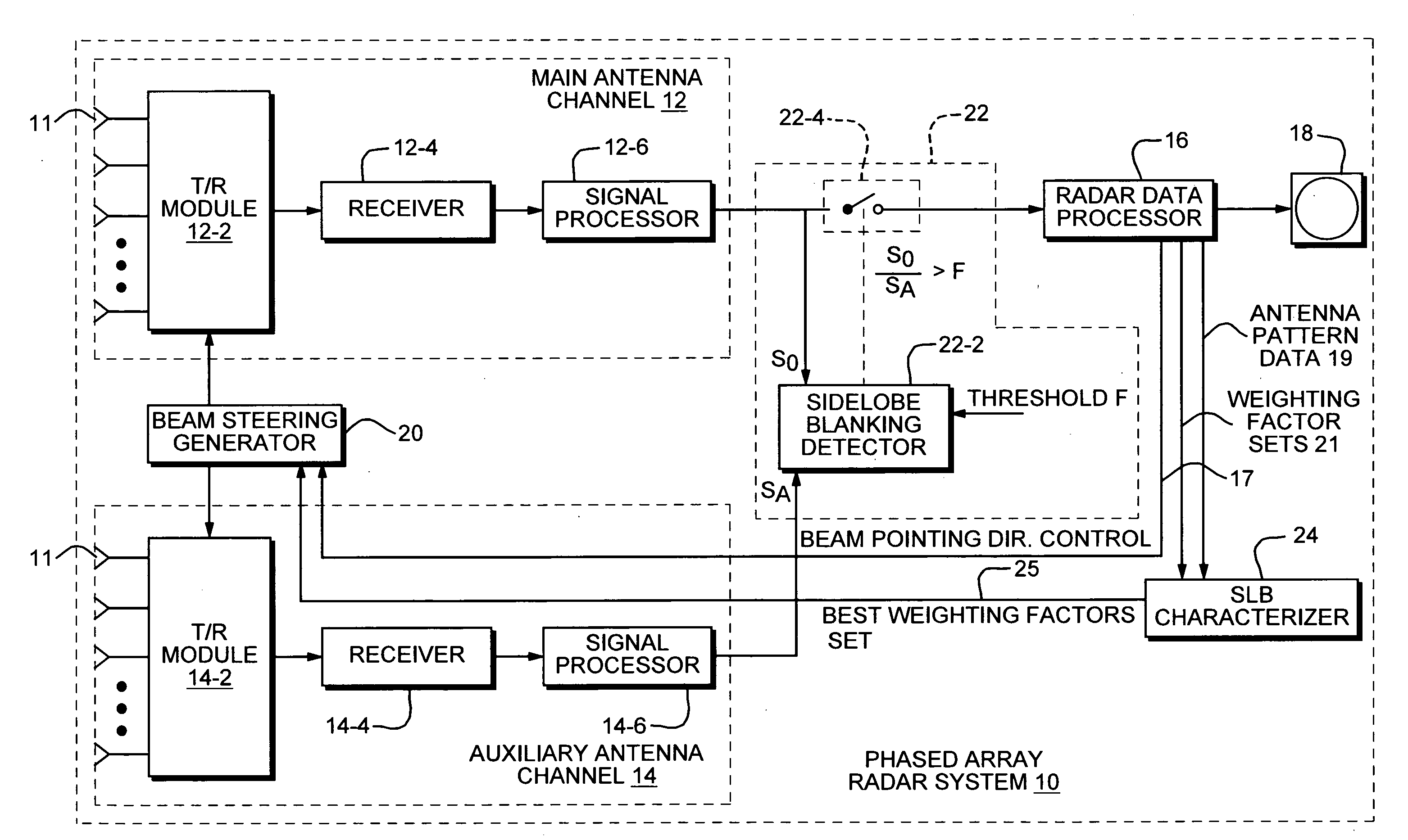
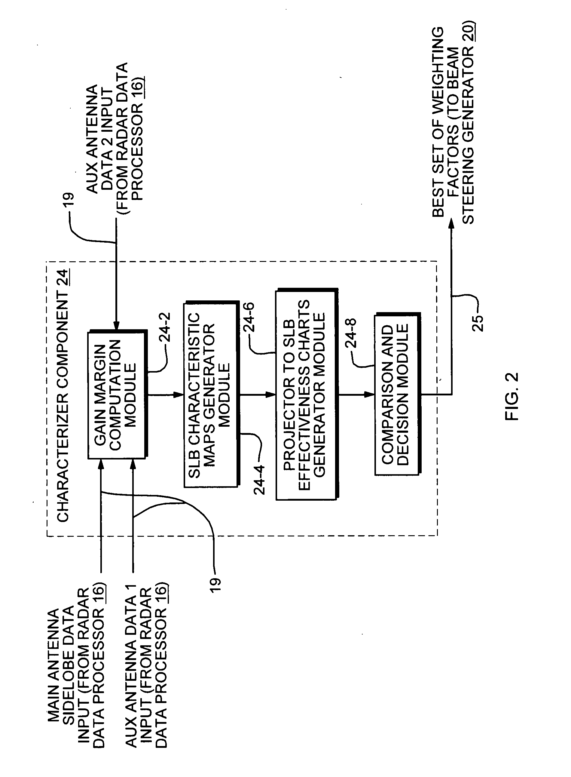
[0014]The above and other objects are achieved according to an illustrated embodiment of the method and system of the present invention which includes a SLB component for improving the effectiveness of sidelobe blanking operations through the combining of multiple dimension data into a single figure of merit comparison. In the illustrated embodiment of a radar system, the SLB component corresponds to a sidelobe blanking characterizer component positioned between a radar data processor and beam steering generator of the radar system. The radar data processor provides several sets of antenna patterns which are used by the characterizer component to compute gain margins according to the teachings of the present invention which takes into account, main beam sidelobe distribution.

Problems solved by technology

In such cases, antenna element failures can seriously impact SLB performance.

Method used


Image

  • Sidelobe blanking characterizer system and method
  • Sidelobe blanking characterizer system and method
  • Sidelobe blanking characterizer system and method

Examples


Embodiment Construction

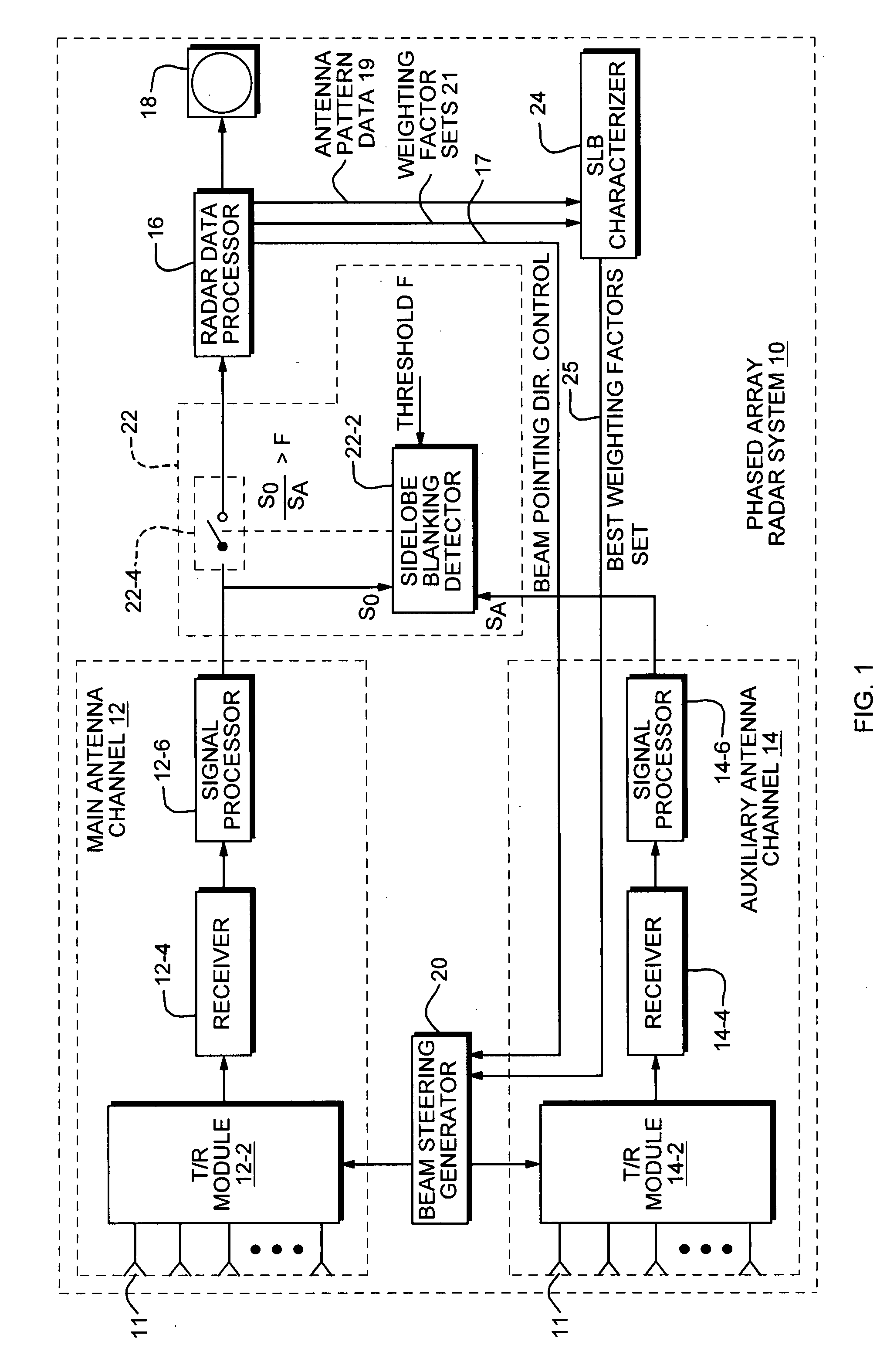
[0039]Referring to FIG. 1, there is shown an illustrative embodiment of the present invention which comprises a phased array radar system 10 incorporating the method and SLB system of the present invention. As shown, system 10 includes a plurality of conventional components that are generally found in a phased array radar system. These components include main and auxiliary antenna channels 12 and 14 respectively, a radar data processor 16 coupled to a display unit 18 and a beam steering generator 20 arranged as shown.

[0040]The system 10 also includes a SLB detector circuit 22 which can also be considered conventional in design and is described in the previously cited articles. According to the teachings of the present invention, the system 10 further includes a SLB characterizer 24 component. The SLB characterizer 24 component is coupled or connected between radar data processor 16 and beam steering generator 30 as shown.

[0041]The components of FIG. 1 will now be described in greate...


PUM


Abstract

The method and system of the present invention includes a SLB characterizer component for achieving optimum sidelobe blanking through the combining of multiple dimension data into a single figure of merit comparison. The SLB characterizer component is positioned between a radar data processor and beam steering generator of a radar system. The radar data processor provides several sets of antenna patterns which are used by the characterizer component to compute gain margins according to the teachings of the present invention. From the computed gain margins, the component generates SLB characteristic maps which provide a much less complex method for evaluating antenna design independent of other system parameters. Based on such SLB characteristic maps, the characterizer component generates SLB effectiveness charts which it uses to compare SLB performance and determine which auxiliary antenna pattern has the best performance. This method is also applicable as a stand alone software tool for auxiliary antenna evaluation and comparison.

Description

[0001]The United States Government has rights to this invention pursuant to Contract No. N00024-04-C-5340 awarded by Department of the Defense.BACKGROUND OF THE INVENTION[0002]1. Field of the Invention[0003]This invention relates generally to antenna system design and more particularly to radar systems that utilize sidelobe blanking (SLB) for suppressing interference signals.[0004]2. Description of Related Art[0005]In many radar applications, stray signals may enter the radar through the sidelobes of the main antenna and may be interpreted as main beam signals. This results in false detections and angle error. Sidelobe blanking (SLB) has been commonly used to suppress such signals when they are impulsive (low duty cycle) whether they are due to sidelobe jammers, strong targets or discrete clutter echoes. The principle of SLB is to inhibit detection when such signals appear in the radar sidelobes.[0006]In his 1968 paper entitled “Performance of Sidelobe Blanking Systems”, Maisel (Pub...

Claims


Application Information

Patent Timeline
IPC IPC(8): G01S3/02
CPCG01S7/2813
Inventor LOK, YUCHOI F.CHANG, KAICHIANG
Owner RAYTHEON CO
Learn More