Image display device, and image display method used for same
- Summary
- Abstract
- Description
- Claims
- Application Information
AI Technical Summary
Benefits of technology
Problems solved by technology
Method used
Image
Examples
first exemplary embodiment
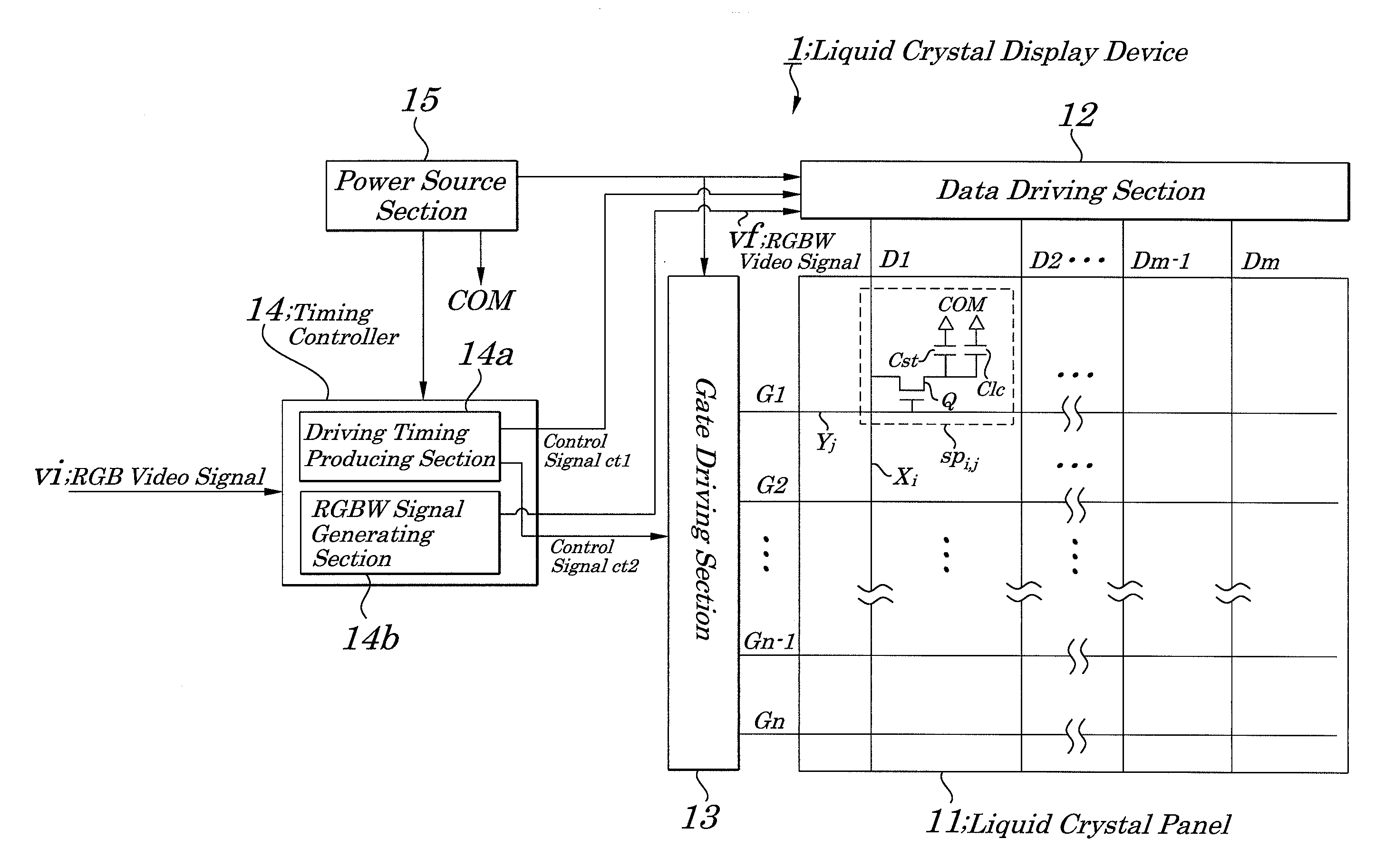
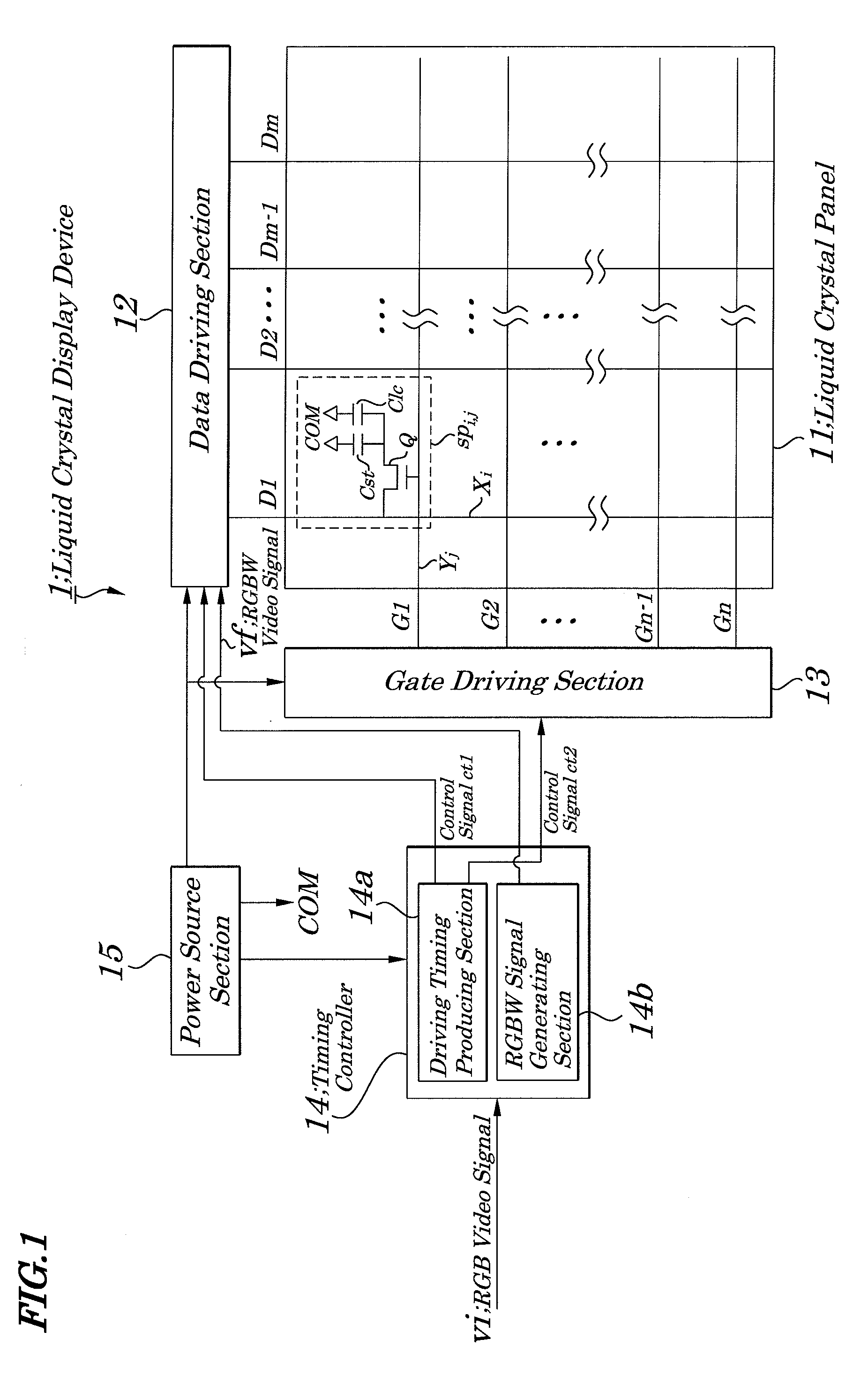
[0047]FIG. 1 is a block diagram showing electrical components of main portions of an image display device of the first exemplary embodiment of the present invention. An example of the image display device of the first exemplary embodiment, as shown in FIG. 1, is a liquid crystal display device 1. The liquid crystal display device 1 includes a liquid crystal panel 11, a data driving section 12, a gate driving section 13, a timing controller 14, and a power source section 15. The liquid crystal panel 11 has signal lines Xi (i=1,2, . . . , m; for example, m=1920), scanning lines Yj (j=1, 2, . . . , n; for example, n=1080) and subpixels SPi, j. To each of the signal lines Xi is supplied a voltage corresponding to a gray level pixel data Di (D1, D2, . . . , Dm−1, Dm) (subpixel gray level signal). To each of the scanning lines Yj is supplied a scanning signal Gj (G1, G2, . . . , Gn−1, Gn) in the order already set. Each of the subpixel SPi,j is mounted in an intersection portion of each of...
second exemplary embodiment
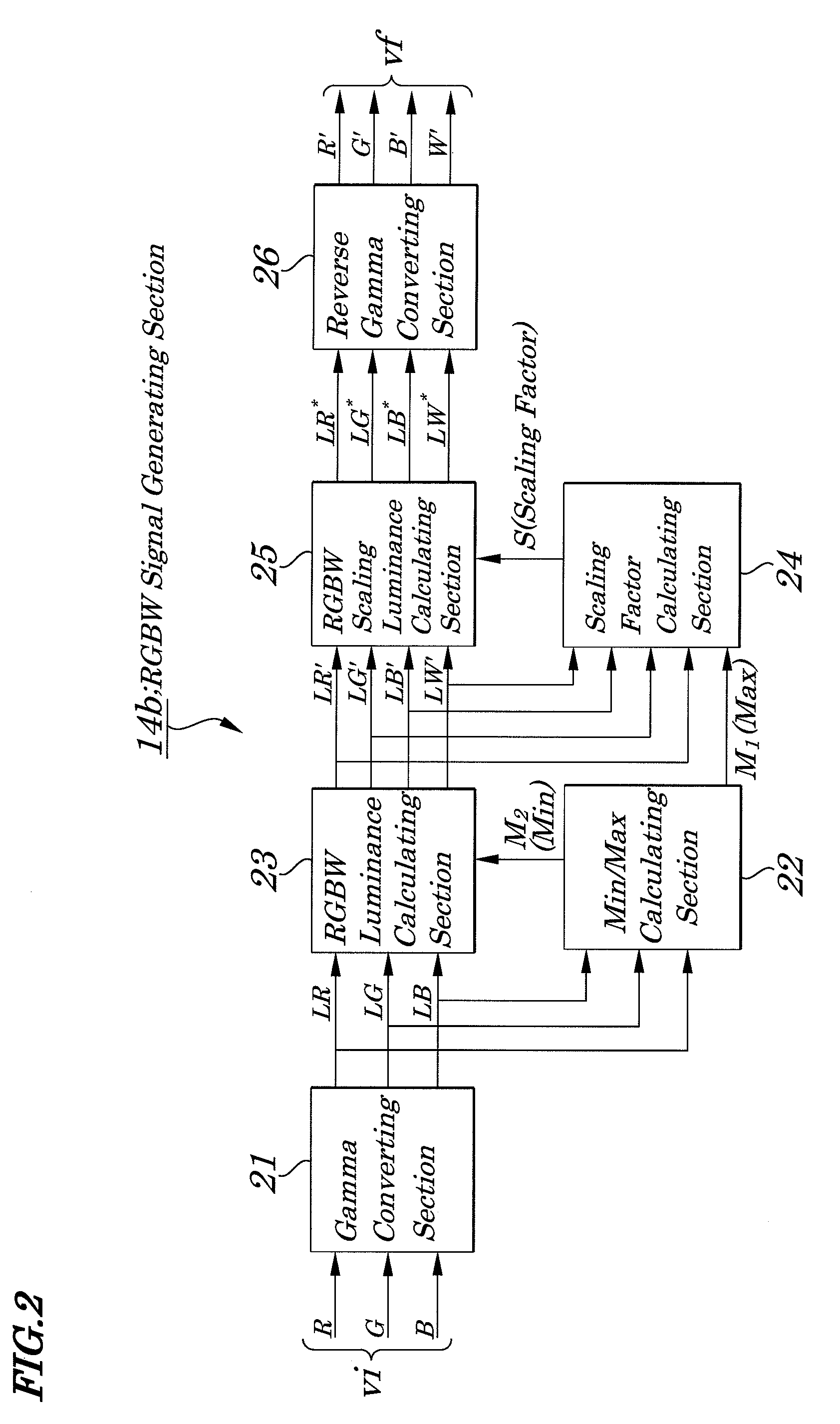
[0074]FIG. 11 is a flow chart explaining other operations of the liquid crystal display device of the second exemplary embodiment of the present invention. In FIG. 11, the same reference is assigned to elements having the same functions as in the first exemplary embodiment in FIG. 7. According to the second exemplary embodiment, in an RGBW signal generating section 14b, an RGB use luminance ratio (three primary color use luminance ratio) is set in which the degree at which gray level values of R, G, and B are used when an RGBW video signal “vf” is generated based on an RGB video signal “vi” is represented as a ratio of a luminance value. The RGB use luminance ratio, when a luminance value is 1 when each of R, G, and B colors is inputted at gray level 255 and when 50% of a gray level value is used, becomes 0.5. Then, a scaling factor calculating section 24 in FIG. 2, when a maximum luminance value M1 is greater than 0, calculates a scaling factor S in a manner to be proportional to t...
third exemplary embodiment
[0076]FIG. 12 is a flow chart explaining other operations of a liquid crystal display device of the third exemplary embodiment of the present invention. The liquid crystal display device has a white subpixel use ratio upper limit value calculating section in which a ratio of a maximum luminance value M1 to a minimum luminance value M2 is calculated, based on the maximum luminance value M1 and the minimum luminance value M2, as an upper value of a ratio of using a white subpixel in an RGBW luminance calculating section 23. Then, the RGBW luminance calculating section 23 in FIG. 2 calculates first four color luminance values LR′, LG′, LB′, and LW′ in a manner in which the minimum luminance value M2 is proportional to any ratio being smaller than the above upper limit value.
[0077]In the liquid crystal display device of the third exemplary embodiment, as shown in FIG. 12, a ratio (M1 / M2) of the maximum luminance value M1 to the minimum luminance value M2 is calculated as the upper limit...
PUM
 Abstract
Description
Claims
Application Information
 - R&D
- Intellectual Property
- Life Sciences
- Materials
- Tech Scout
- Unparalleled Data Quality
- Higher Quality Content
- 60% Fewer Hallucinations
Browse by: Latest US Patents, China's latest patents, Technical Efficacy Thesaurus, Application Domain, Technology Topic, Popular Technical Reports.
© 2025 PatSnap. All rights reserved.Legal|Privacy policy|Modern Slavery Act Transparency Statement|Sitemap|About US| Contact US: help@patsnap.com


