Backlight apparatus

a backlight apparatus and backlight technology, applied in lighting apparatus, light sources, instruments, etc., can solve problems such as inability to effectively improve the prior art, reduce power consumption, and prevent the increase of the temperature of the switch.

Inactive Publication Date: 2009-04-23
CHUNGHWA PICTURE TUBES LTD
View PDF7 Cites 3 Cited by
  • Summary
  • Abstract
  • Description
  • Claims
  • Application Information

AI Technical Summary

Benefits of technology

[0011]The present invention is directed to a backlight apparatus which can reduce power consumption, prevent a temperature increase of the apparatus and improve an effect caused by a temperature increase of an LED, so that the whole efficiency can be greatly improved.
[0017]The present invention adopts the design of a feedback circuit, so that the voltage converter can dynamically modify the inner periodic signal according to a feedback signal and changes the outputted rated voltage. Therefore, the disadvantages in the prior arts can be effectively improved, and the temperature of the switch is prevented from increasing. In addition, by adjusting the rated voltage dynamically, the power consumption is reduced, the temperature of the apparatus is prevented from increasing, and therefore the whole efficiency can be greatly improved.

Problems solved by technology

The problem is caused by an extra voltage absorbed by the switch when the temperature of a light emitting diode (LED) increases as a forward voltage thereof decreases.

Method used


Image

  • Backlight apparatus
  • Backlight apparatus
  • Backlight apparatus

Examples


Embodiment Construction

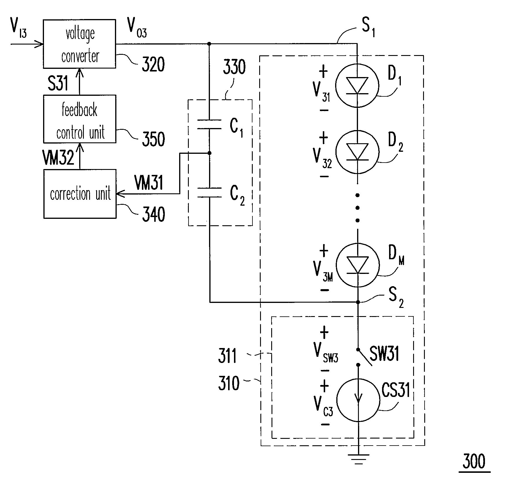
[0026]FIG. 3A is a schematic view illustrating the structure of a backlight apparatus 300 according to an embodiment of the present invention. Referring to FIG. 3A, the backlight apparatus 300 includes a light emitting unit 310, a voltage converter 320, a voltage detection unit 330, a correction unit 340, and a feedback control unit 350. The light emitting unit 310 has a first connection end S1 and a second connection end S2. The first connection end S1 is electrically connected to an output end of the voltage converter 320 while the second connection end S2 is electrically connected to the voltage detection unit 330.

[0027]The voltage detection unit 330 is electrically connected between the first connection end S1 and the second connection end S2 to detect a voltage level of the two connection ends, so as to generate a measuring voltage VM31. The correction unit 340 is electrically connected to the voltage detection unit 330 and the feedback control unit 350 in order to correct the ...


PUM


Abstract

A backlight apparatus is provided. The apparatus includes a light emitting unit, a voltage converter, a voltage detection unit, a correction unit, and a feedback control unit. The light emitting unit has a first connection end and a second connection end. The voltage converter transforms an input voltage into a rated voltage according to a periodic signal. The voltage detection unit detects a voltage level on the first connection end and the second connection end, and generates a measuring voltage. The correction unit performs a gain correction of the measuring voltage and adjusts the corrected measuring voltage by a specific ratio to generate a correction voltage. The feedback control unit outputs a feedback signal according to the correction voltage, and the voltage converter dynamically modifies the periodic signal according the feedback signal.

Description

CROSS-REFERENCE TO RELATED APPLICATION[0001]This application claims the priority benefit of Taiwan application serial no. 96139006, filed on Oct. 18, 2007. The entirety of the above-mentioned patent application is hereby incorporated by reference herein and made a part of specification.BACKGROUND OF THE INVENTION[0002]1. Field of the Invention[0003]The present invention relates to a backlight apparatus of a display, and in particular, to a backlight apparatus for dynamically correcting a driving voltage of a light emitting diode.[0004]2. Description of Related Art[0005]Liquid crystal displays (LCD) are the mainstream products in the display market. Due to the advantageous features provided by the LCDs, namely, high definition, low power consumption, thinness and massive production, a low operating voltage, small and compact size, LCDs have become the mainstream display screens of the products including small portable TVs, image phones, digital camcorders, digital players, notebooks,...

Claims


Application Information

Patent Timeline
Patent Type & Authority Applications(United States)
IPC IPC(8): G09G3/36
CPCH05B33/0827H05B33/0815H05B45/37H05B45/46
Inventor LIN, CHI-HSIULIN, SHIN-CHANG
Owner CHUNGHWA PICTURE TUBES LTD
Why Eureka
Try Eureka