Air pump having selectable low pressure and high pressure mode

a low pressure and high pressure technology, applied in the field of air pumps, can solve the problems of inconvenient operation, big cylinders at the rear end will lose efficacy by turning the knob, and the effect of improving inflation efficiency

Active Publication Date: 2009-04-23
WANG LOPIN
View PDF13 Cites 20 Cited by
  • Summary
  • Abstract
  • Description
  • Claims
  • Application Information

AI Technical Summary

Benefits of technology

[0012]The primary object of the present invention is to provide an air pump having selectable low pressure and high pressure mode and also has better inflation efficiency and convenience operation.

Problems solved by technology

The big cylinder at rear end will lose efficacy by turning the knob.
A pressure relief valve is provided at front and the big cylinder will lose efficacy by opening the valve also.
But, there is a disadvantage of reorganization if the pressure relief valve operates by the way of rotation.
This is more inconveniently then patent 529 to put the big cylinder into the very dense steel wires of the steel rim because that the small cylinder in patent 529 is provided at front.

Method used


Image

  • Air pump having selectable low pressure and high pressure mode
  • Air pump having selectable low pressure and high pressure mode
  • Air pump having selectable low pressure and high pressure mode

Examples


Embodiment Construction

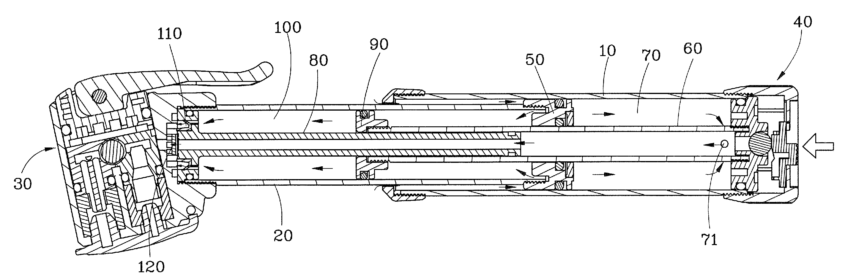
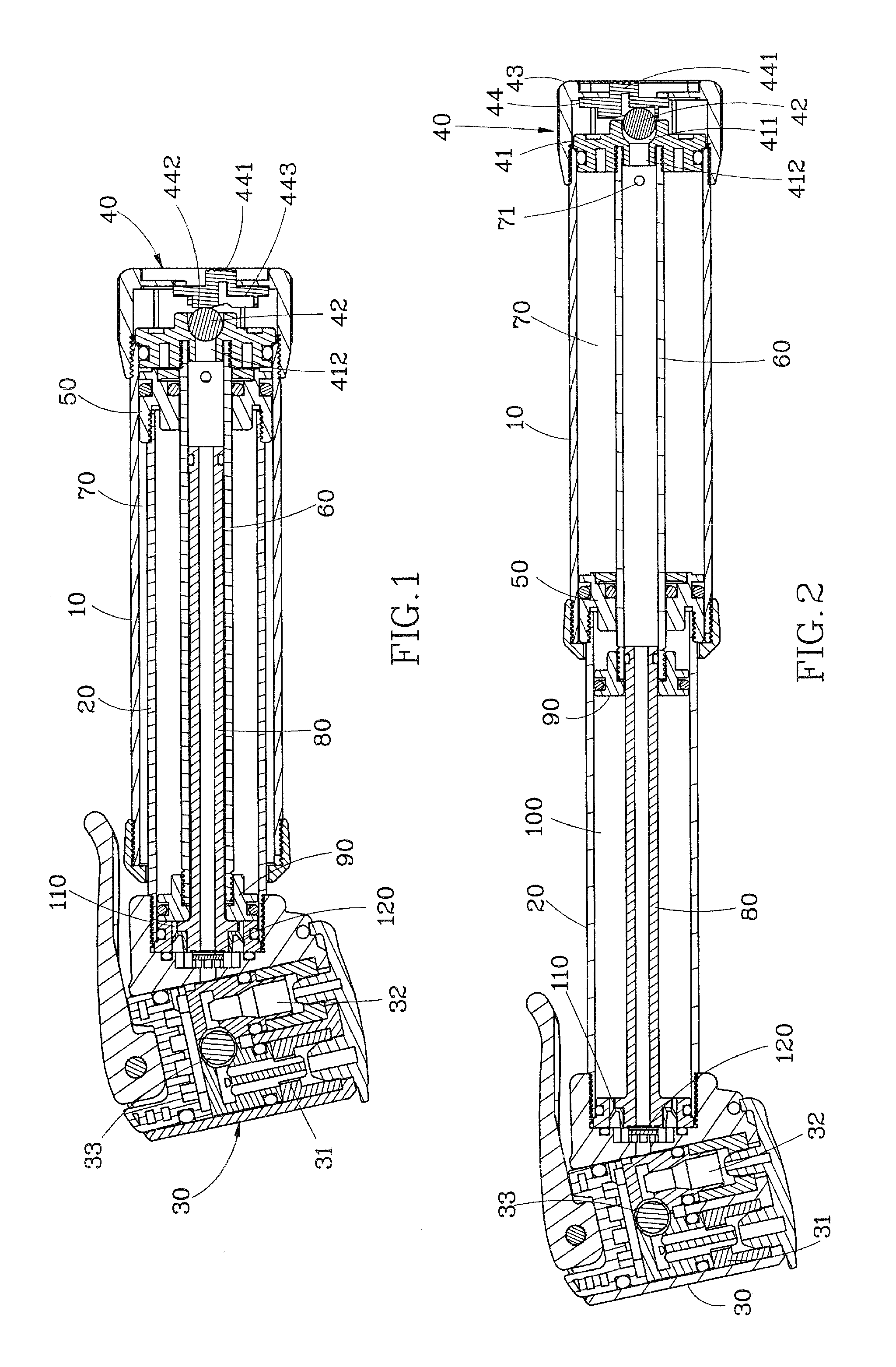
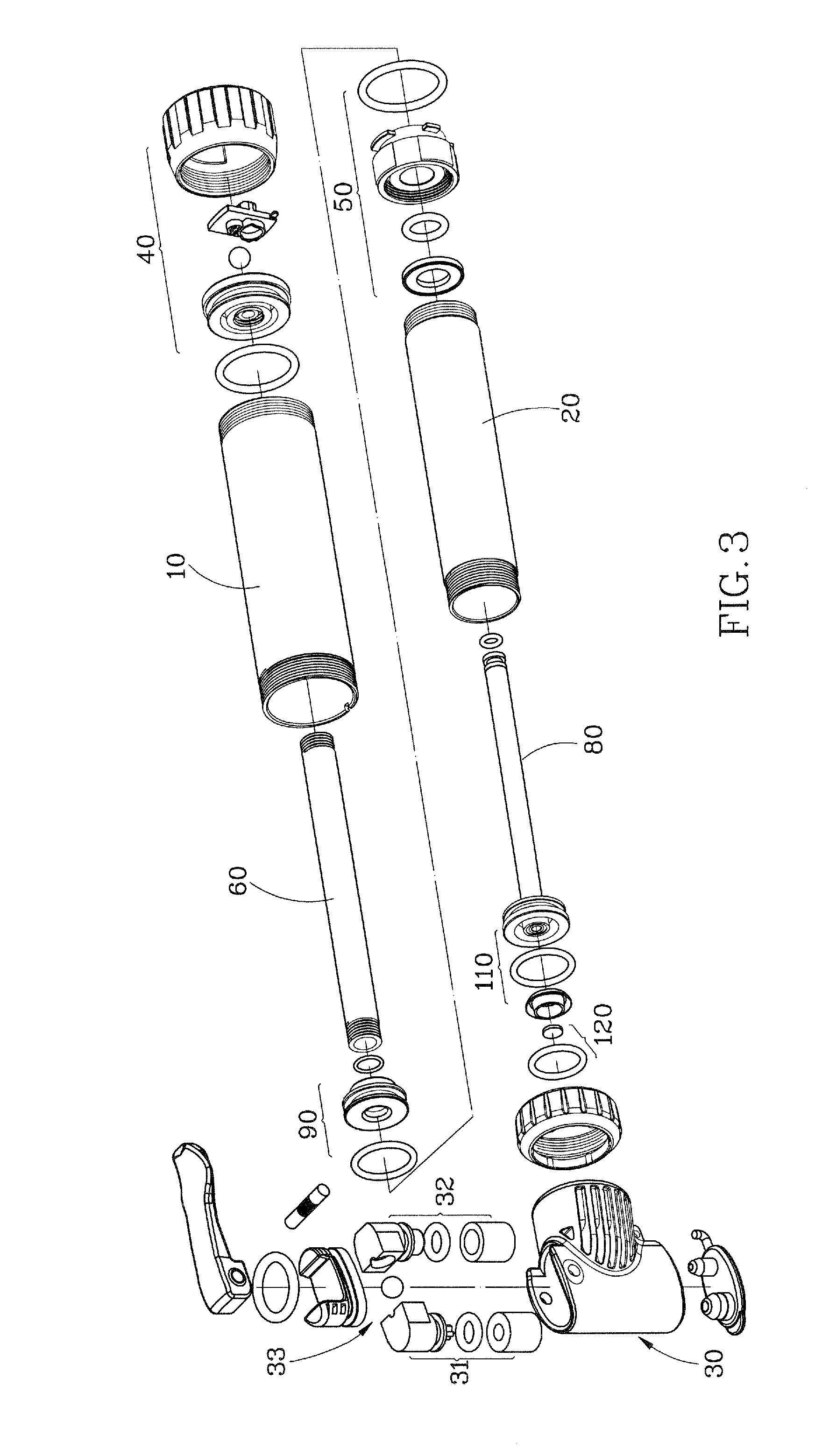
[0020]Referring to FIG. 1, FIG. 2 and FIG. 3, the air pump of present invention, including:

[0021]A big cylinder 10 and a small cylinder 20 expandable are fitted to each other.

[0022]A head 30 connects with the out end of said small cylinder 20.

[0023]A pressure relief valve 40 connects with the out end of said big cylinder 10.

[0024]A first piston 50 fixes at the in end of said small cylinder and is placed inside said big cylinder 10.

[0025]A first pipe 60, one end fixes on the out end of said big cylinder 10 and places inside said big cylinder 10, and the other passes through said first piston 50 and places inside said small cylinder 20.

[0026]A first chamber 70 with a passage 71 communicating with said first pipe 60 forms therein between the inside wall of said big cylinder 10 and the outside wall of said first pipe 60 and between the out end of said big cylinder 10 and said first piston 50. Said passage 71 is a hole that is provided on said first pipe 60 near to the out end in this em...


PUM


Abstract

An air pump, including: two cylinders, a big one and a small one, is fitted to each other by a contractible way. A head connects with the out end of the small cylinder. A pressure relief valve connects with the out end of the big cylinder. A first piston is fixed at the in end of the small cylinder and placed in the big cylinder. A first pipe, one end fixes on the out end of the big cylinder, and the other passes through the first piston and places inside the small cylinder. A first chamber with a passage communicating with the first pipe forms therein between the inside wall of the big cylinder and the outside wall of the first pipe. A second pipe, one end fixes at the out end of the small cylinder and communicates with the head in one-way air admission and the other fits into the first pipe by contractible way and communicates with it. A second piston, which is placed inside the small cylinder, fixes at the other end of the first pipe and the second pipe goes through it. A second chamber with a one-way passage communicating with the head forms therein between the inside wall of the small cylinder and the outside wall of the second pipe and between the out end of the small cylinder and the second piston.

Description

BACKGROUND OF THE INVENTION[0001]1. Field of the Invention[0002]The present invention relates to an air pump and more particular to an air pump having selectable low pressure and high pressure mode.[0003]2. Description of the Related Art[0004]In the prior art, U.S. Pat. No. 5,165,876 discloses a telescope air pump with two cylindrical bodies. One cylindrical body is fitted to one end of the other cylindrical body. There is a piston rod and a two-way air admission piston provided therein. So, the air pump can be divided into three air chambers. The air pump inflates an object when it is pushed or pulled.[0005]U.S. Pat. No. 5,443,370 discloses a telescope air pump with three divisible cylinders. By increasing the route of push and pull, the air pump increases the air quantity in every stroke motion. The two adjacent cylinders can be locked together to make the big cylinder invalid and only two small cylinders keep working in high pressure mode.[0006]U.S. Pat. No. 5,676,529 discloses a...

Claims


Application Information

Patent Timeline
Patent Type & Authority Applications(United States)
IPC IPC(8): F04B1/02F04B19/02F04B33/00
CPCF04B33/005F04B19/022
Inventor WANG, LOPIN
Owner WANG LOPIN
Why Eureka
Try Eureka