Assisted stack anode purge at start-up of fuel cell system

Active Publication Date: 2009-04-23
GM GLOBAL TECH OPERATIONS LLC
View PDF3 Cites 33 Cited by
  • Summary
  • Abstract
  • Description
  • Claims
  • Application Information

AI Technical Summary

Benefits of technology

[0008]In concordance with the instant disclosure, a fuel cell system and method that provide an efficient start-up that meets hydrogen exhaust emission standards and minimizes hydrogen-air front time and stack degradation, is surprisingly discovered.

Problems solved by technology

However, the rate of fill can be limited by pressure limitations of the fuel cell stack and flow resistances across the fuel cell system.
However, carbon corrosion may also be caused by a non-simultaneous delivery of hydrogen to the fuel cells.
For example, the fuel cells nearest the hydrogen supply may receive hydrogen first, and the short circuit is not effective until most of the fuel cells have received hydrogen.
Thus, the fuel cells that receive hydrogen first may experience unmitigated corrosion due to the hydrogen-air front.
However, the fuel cells that do not have hydrogen may experience a negative voltage in a phenomenon known as “cell reversal.” Cell reversal also results in an undesirable carbon corrosion of the fuel cell stack.
However, due to the inconsistent conditions of the fuel cell system following a shut-down period, such as a variable quantity of accumulated air on the anodes, known fuel cell systems are not particularly effective in optimizing hydrogen emissions during start-up.

Method used


Image

  • Assisted stack anode purge at start-up of fuel cell system
  • Assisted stack anode purge at start-up of fuel cell system
  • Assisted stack anode purge at start-up of fuel cell system

Examples


Embodiment Construction

[0018]The following description is merely exemplary in nature and is not intended to limit the present disclosure, application, or uses. It should also be understood that throughout the drawings, corresponding reference numerals indicate like or corresponding parts and features. In respect of the methods disclosed, the steps presented are exemplary in nature, and thus, are not necessary or critical.

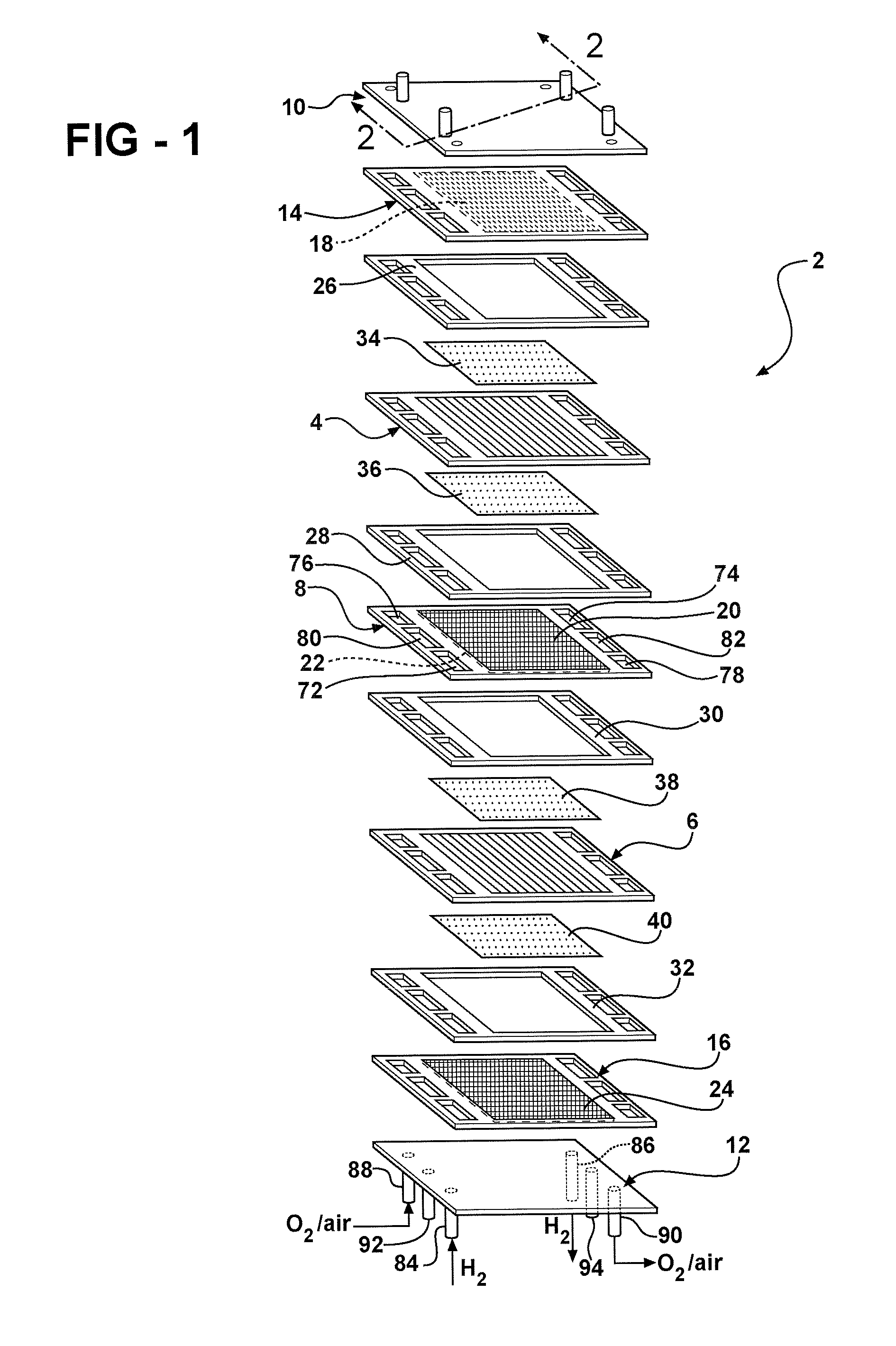
[0019]FIG. 1 depicts a fuel cell stack 2 having a pair of MEAs 4, 6 separated from each other by an electrically conductive bipolar plate 8. For simplicity, only a two-cell stack (i.e. one bipolar plate) is illustrated and described in FIG. 1, it being understood that a typical fuel cell stack will have many more such cells and bipolar plates.

[0020]The MEAs 4, 6 and bipolar plate 8 are stacked together between a pair of clamping plates 10, 12 and a pair of unipolar end plates 14, 16. The clamping plates 10, 12 are electrically insulated from the end plates 14, 16 by a gasket or a dielectr...


PUM


Abstract

A fuel cell system that enables an assisted anode purge upon start-up is provided. The fuel cell system includes a fuel cell stack having a plurality of fuel cells with anodes and cathodes. The fuel cell stack has an anode supply manifold and an anode exhaust manifold in fluid communication with the anodes. The fuel cell system further includes a suction device in fluid communication with at least one of the anode supply manifold and the anode exhaust manifold. The suction device adapted to selectively draw a partial vacuum on the fuel cell stack during a start-up of the fuel cell system. Methods for starting the fuel cell system are also provided.

Description

FIELD OF THE INVENTION[0001]The present disclosure relates to a fuel cell system and, more particularly, to a start-up system and method for purging anodes of a fuel cell stack at start-up.BACKGROUND OF THE INVENTION[0002]A fuel cell has been proposed as a clean, efficient and environmentally responsible power source for electric vehicles and various other applications. In particular, the fuel cell has been identified as a potential alternative for the traditional internal-combustion engine used in modern vehicles.[0003]One type of fuel cell is known as a proton exchange membrane (PEM) fuel cell. The PEM fuel cell typically includes three basic components: a cathode electrode, an anode electrode, and an electrolyte membrane. The cathode and anode electrodes typically include a finely divided catalyst, such as platinum, supported on carbon particles and mixed with an ionomer. The electrolyte membrane is sandwiched between the cathode and the anode to form a membrane-electrode-assembl...

Claims


Application Information

Patent Timeline
IPC IPC(8): H01M8/02
CPCH01M8/04089H01M8/04223Y02E60/50H01M2008/1095H01M8/04231H01M8/04225H01M8/04302H01M8/2483
Inventor MACHUCA, JOE C.MACKINTOSH, CHARLESROBB, GARY M.
Owner GM GLOBAL TECH OPERATIONS LLC
Why Eureka
Try Eureka