Avoiding Drift Engagement of a Hydraulic Clutch

a technology of hydraulic clutch and control element, which is applied in the direction of non-mechanical actuated clutches, clutches, instruments, etc., can solve the problems of few design compromises, virtually no sensible effect on vehicle operation or performance, and control produces few design compromises

Inactive Publication Date: 2009-04-23
FORD GLOBAL TECH LLC
View PDF4 Cites 17 Cited by
  • Summary
  • Abstract
  • Description
  • Claims
  • Application Information

AI Technical Summary

Benefits of technology

[0009]A method for controlling speed of an input shaft to a hydraulically actuated clutch that includes a hydraulic balance dam volume includes determining a limit speed of the input shaft that varies as a function of time during a predetermined period and while the input shaft rotates and that causes a servo piston for actuating the clutch to mo...

Problems solved by technology

The control produces few design compromises and has vir...

Method used


Image

  • Avoiding Drift Engagement of a Hydraulic Clutch
  • Avoiding Drift Engagement of a Hydraulic Clutch
  • Avoiding Drift Engagement of a Hydraulic Clutch

Examples


Embodiment Construction

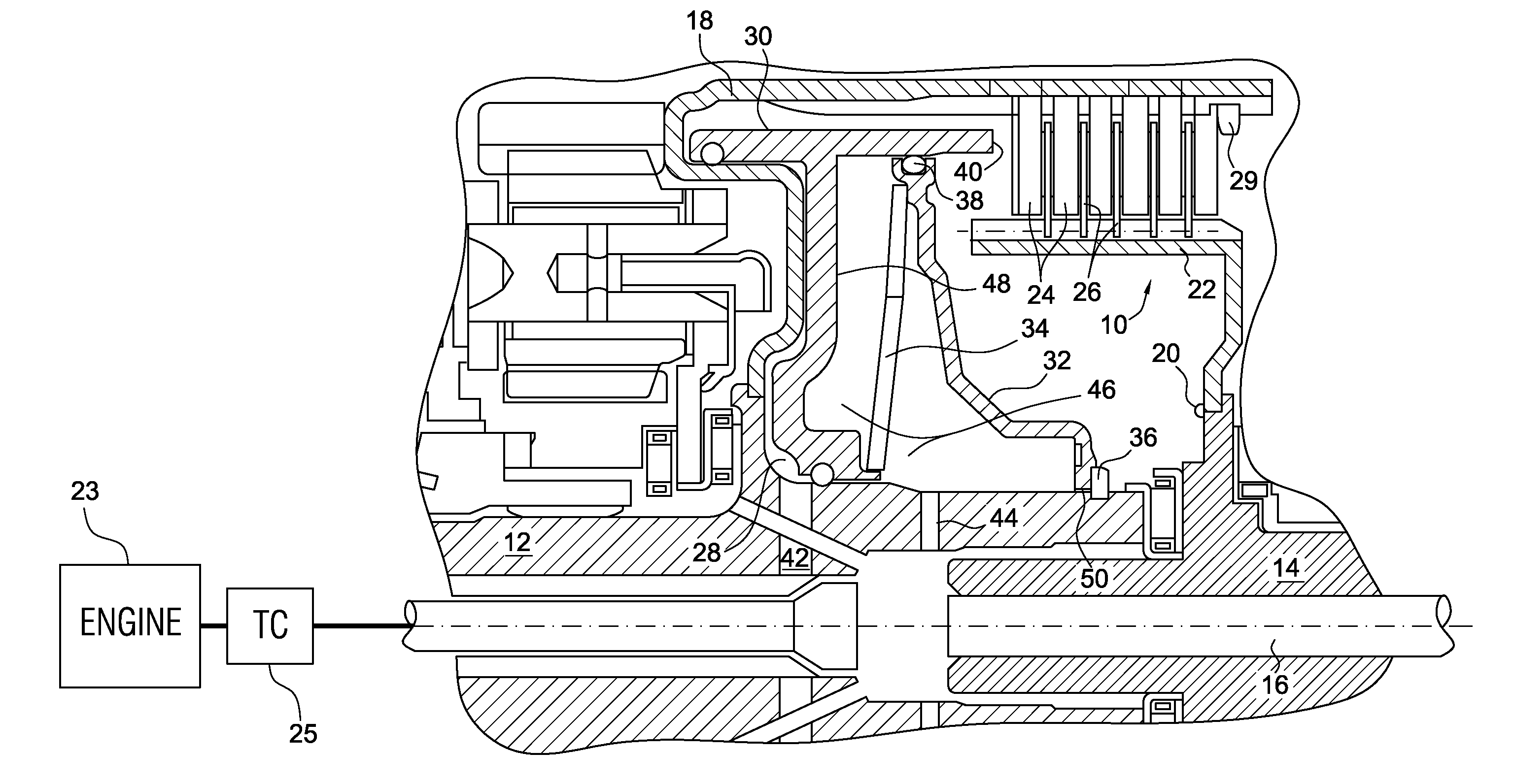
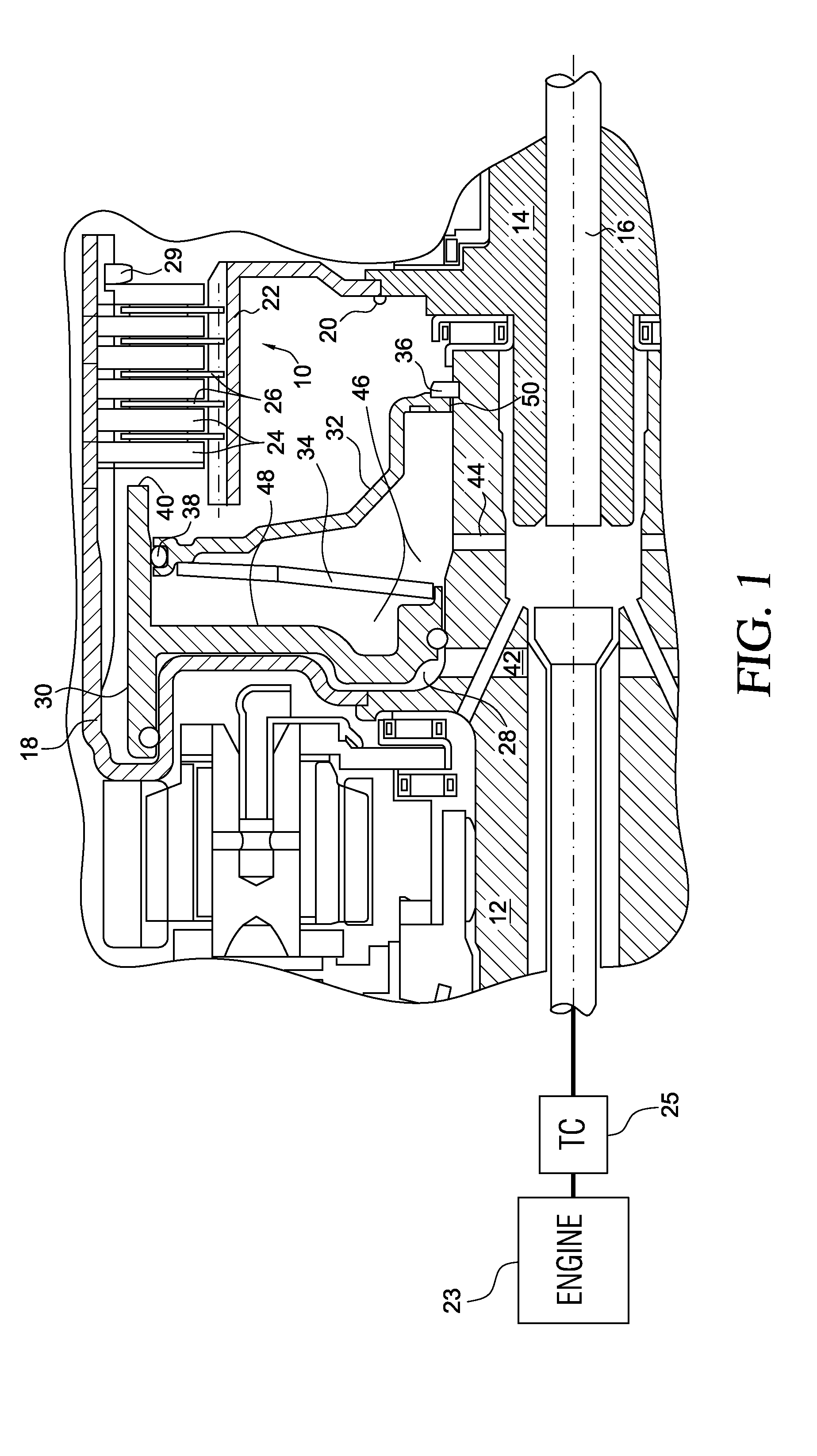
[0017]The clutch 10 shown in FIG. 1 alternately driveably connects and disconnects a clutch input shaft 12 and a shaft 14, which are supported for rotation about a central axis 16 within the casing of an automatic transmission. Shaft 12 is secured by a weld to a rotating drum 18, and shaft 14 is secured by a weld 20 to a rotating drum 22. Clutch input shaft 12 is driveably connected to an engine 23 through a torque converter 25. The inner surface of drum 18 is formed with a longitudinal spline, which is engaged by external splines formed on a series of spacer plates 24. Similarly, the external surface of drum 22 is formed with a longitudinal spline, which is engaged by internal splines formed on a series of friction discs 26, each disc being interleaved between two consecutive spacer plates 24.

[0018]Drum 18 defines the surface of a hydraulic cylinder 28, within which are located an axially displaceable piston 30, a balance dam 32, and return spring 34. Piston 30 carries a seal that ...


PUM


Abstract

A method for controlling speed of an input shaft to a hydraulically actuated clutch that includes a hydraulic balance dam volume includes determining a limit speed of the input shaft that varies as a function of time during a predetermined period after the clutch starts rotation and that causes a servo piston for actuating the clutch to move toward an engaged position, rotating the input shaft during the period, limiting a speed of the input shaft during said period to a determined limit speed corresponding to a current time after beginning the period, and allowing the speed of the input shaft to increase to a speed greater than the determined limit speed after expiration of the period.

Description

BACKGROUND OF THE INVENTION[0001]1. Field of the Invention[0002]This invention relates generally to a hydraulically actuated control element of an automatic transmission, such as a clutch or brake, having a balance dam.[0003]2. Description of the Prior Art[0004]A balance dam is a device used in a hydraulically actuated clutch to reduce differential pressure across a piston of an actuating servo induced by centrifugal force.[0005]Many balance dams include a vent near the inside diameter of the balance piston. This vent is intended to both allow oil to exit the balance dam when the clutch-apply piston strokes to engage a clutch and also to reduce the pressure in the balance dam cavity during normal operation. However, the balance cavity dam will at least partially empty through the vent when the clutch is stationary and when the engine is not running.[0006]After the balance dam is partially drained and upon restarting the engine, the balance dam does not contain enough oil to function...

Claims


Application Information

Patent Timeline
IPC IPC(8): G06F19/00
CPCF16D25/0638F16D2500/70454F16D48/06
Inventor GOODEN, JAMES T.RIEDLE, BRADLEY D.O'NEIL, BRIAN M.
Owner FORD GLOBAL TECH LLC
Why Eureka
Try Eureka