Bearing unit

a bearing shell and bearing shell technology, applied in the direction of roller bearings, needle bearings, bearing unit rigid support, etc., can solve the problems of requiring precise mounting control, and affecting the position of the bearing shell, so as to achieve good positional securing of the bearing shell

Inactive Publication Date: 2010-12-02
SCHAEFFLER TECH AG & CO KG
View PDF3 Cites 1 Cited by
  • Summary
  • Abstract
  • Description
  • Claims
  • Application Information

AI Technical Summary

Benefits of technology

[0008]It is an object of the invention to propose a bearing unit which, taking the production and mounting expe

Problems solved by technology

Therefore, differently from documents DE 26 11 218 A1, DE 39 31 447 A1 and DE 101 53 432 C1, plastic deformation does not take place (exclusively) in order to form a projection during mounting; this makes mounting complicated and requires precise mounting control (in certain circum

Method used


Image

  • Bearing unit
  • Bearing unit
  • Bearing unit

Examples


Embodiment Construction

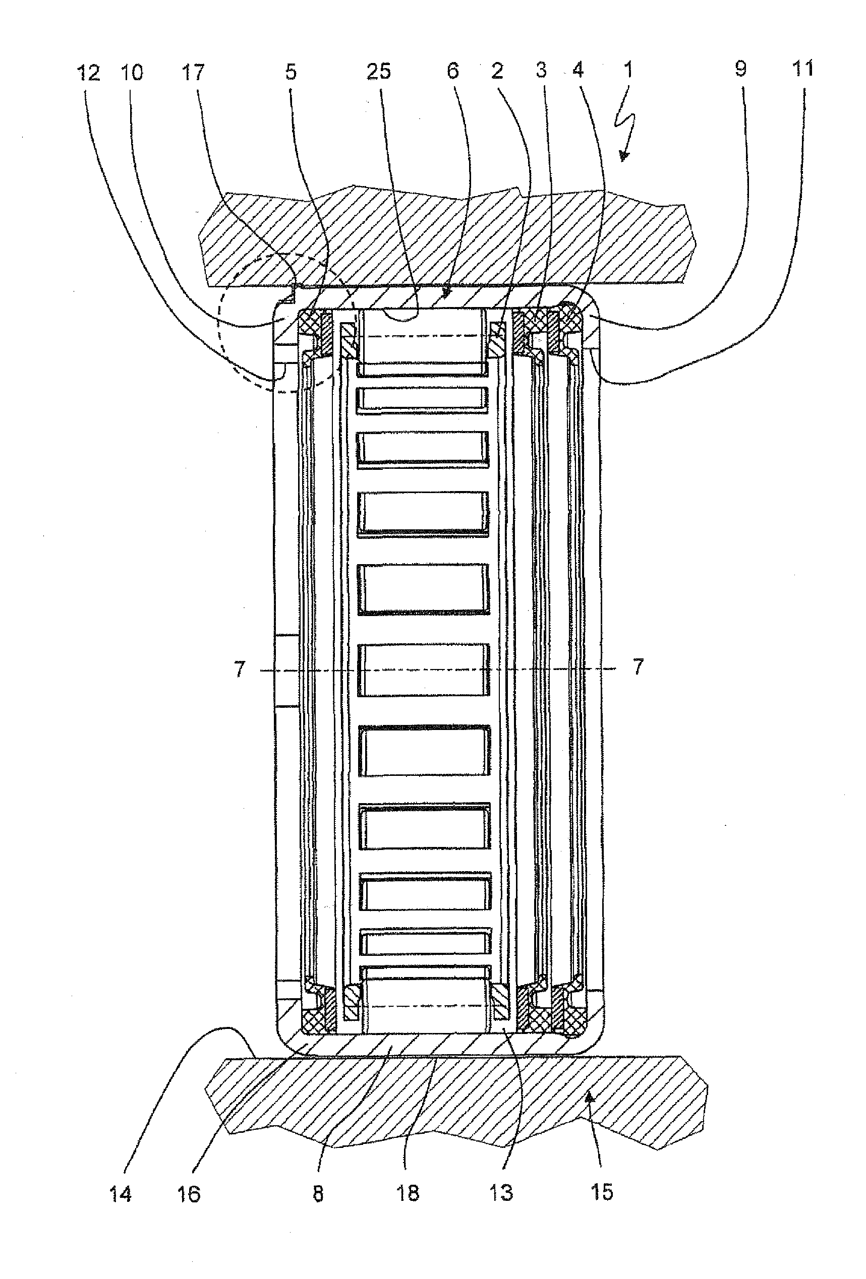
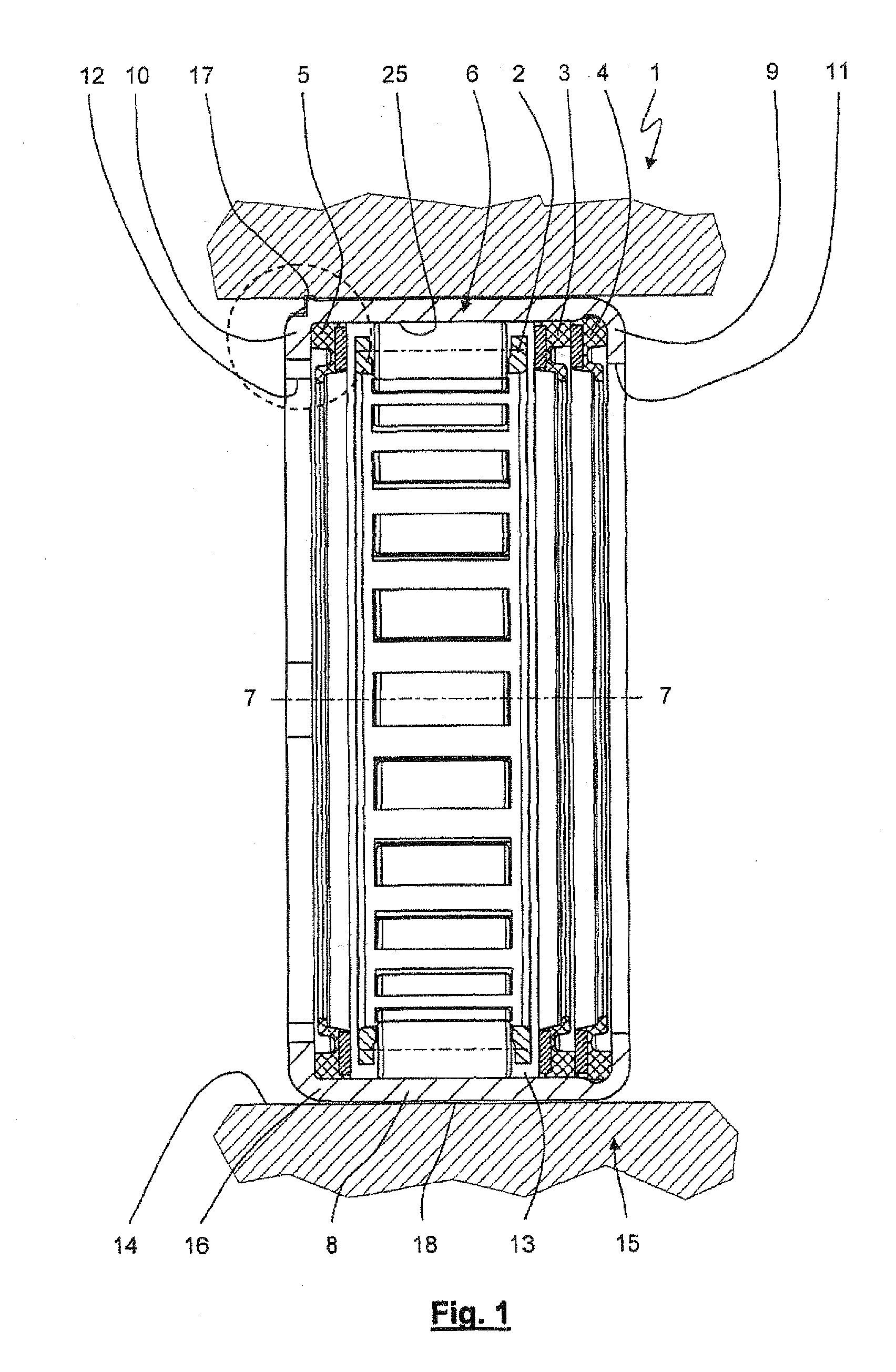
[0038]FIG. 1 shows a bearing unit 1 which is formed with a bearing cage 2, seals 3, 4, 5 arranged here on both sides of the bearing cage 2, and a bearing shell 6. The bearing shell 6 is U-shaped in a half longitudinal section with respect to the longitudinal axis or bearing axis 7-7, with a base limb 8 oriented parallel to the bearing axis 7-7 and two side limbs 9, 10 of approximately equal length which extend radially inward from the base limb 8. Owing to the shaping of the side limbs 9, 10, whereby the latter are unwound from a semifinished product, the transition regions between the base limb 8 and side limbs 9, 10 have a rounded design. End faces 11, 12 of the side limbs 9, 10 form bore for the passage of a shaft (not shown in the figures). Together with the bearing shell 6, this shaft forms a hollow-cylindrical circumferential inner space 13 of the bearing unit 1 with radial gaps between the end faces 11, 12 and the shaft, the inner space 13 being sealed by means of the seals 3...


PUM


Abstract

A bearing unit which has a bearing shell with a projection which plastically deforms a bore of an adjacent component, on assembly, to produce a recess, thereby securing the bearing shell against being axially displaced in the direction of a bearing axis and from being twisted in the peripheral direction. The position and anti-twist locking effect is thus achieved by producing a recess in the adjacent component in which recess the projection is accommodated in a positive fit. The bearing unit is preferably used for bearing a starter shaft in a starter of a motor vehicle.

Description

FIELD OF THE INVENTION[0001]The present invention relates to a bearing unit, in particular for a starter of a motor vehicle, a throttle valve, a diesel assembly or a radial piston pump.BACKGROUND OF THE INVENTION[0002]In the case of bearing units, it must be ensured that the position of a bearing shell with respect to an adjacent or adjoining component (referred to hereinafter as “adjacent component”) is maintained, even during operation of the bearing unit and when thermal expansions occur for operationally induced temperature changes, in which case axial migration of the bearing shell and / or rotation of the bearing shell with respect to the adjacent component should be avoided, for example. For this purpose, it is known from the prior art to support the bearing shell with a press fit with a very large oversize with respect to the adjacent component. Alternatively or in addition, it is possible to provide securing using a mechanical element, for example a securing ring or a nut, or...

Claims


Application Information

Patent Timeline
IPC IPC(8): F16C19/46
CPCF02N15/00F16C19/26F16C33/588F16C35/067F16C33/586F16C33/78
Inventor ANGER, ANDRESCHARINGER, KLAUS
Owner SCHAEFFLER TECH AG & CO KG
Why Eureka
Try Eureka