Fluid dispensers and methods for dispensing viscous fluids with improved edge definition

a dispenser and viscous fluid technology, applied in the direction of liquid/solution decomposition chemical coating, superimposed coating process, manufacturing tools, etc., can solve the problems of poor edge definition for atomizing spray or patterned fluid application, intermittent flow discontinuities, and limited approach to low viscosity fluids. achieve the effect of reducing dead volume and high frequency operation

Inactive Publication Date: 2009-04-30
NORDSON CORP
View PDF12 Cites 30 Cited by
  • Summary
  • Abstract
  • Description
  • Claims
  • Application Information

AI Technical Summary

Benefits of technology

[0008]The fluid dispenser(s) and nozzle plate are capable of dispensing a variety of different types of fluids and permits tight control over the film build or thickness on the substrate. The fluid dispenser(s) and nozzle plate are capable of accurate edge definition because, at least in part, of the rectilinear or trapezoidal pattern dispensed from the nozzle array that, as the fluid dispenser(s) are moved relative to the substrate, overlap and define a strip of fluid deposited on the substrate. As a consequence, the fluid dispenser(s) can dispense fluid onto more densely packed objects on a substrate.
[0010]The construction of the nozzle plate, in conjunction with high frequency operation and low duty cycles, causes the fluid ejected from the nozzles to travel in a direction that is approximately parallel to the centerline of the discharge passageway in each nozzle. The fluid cavity has dimensions optimized to minimize the dead volume and enable high frequency operation.

Problems solved by technology

Hence, cyclic movement between the opened and closed positions causes intermittent flow discontinuities necessary to generate a pattern of fluid on a surface of the product or product packaging.
However, this approach is limited to low viscosity fluids and deposits on the substrate with a film thickness that varies with position between the edges of the fan spray.
However, edge definition may be poor for atomizing sprays or patterned fluid application.

Method used


Image

  • Fluid dispensers and methods for dispensing viscous fluids with improved edge definition
  • Fluid dispensers and methods for dispensing viscous fluids with improved edge definition
  • Fluid dispensers and methods for dispensing viscous fluids with improved edge definition

Examples


Embodiment Construction

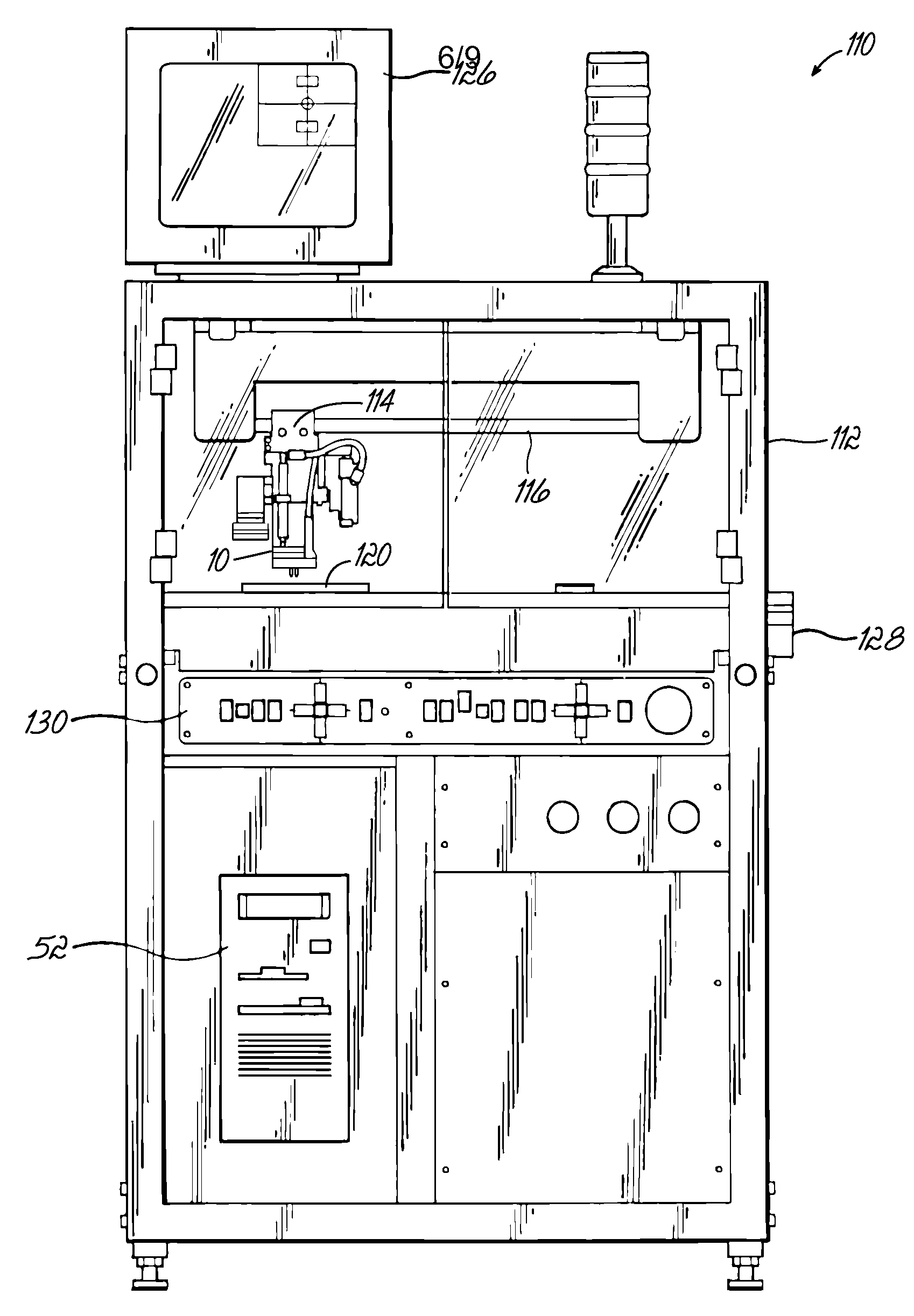
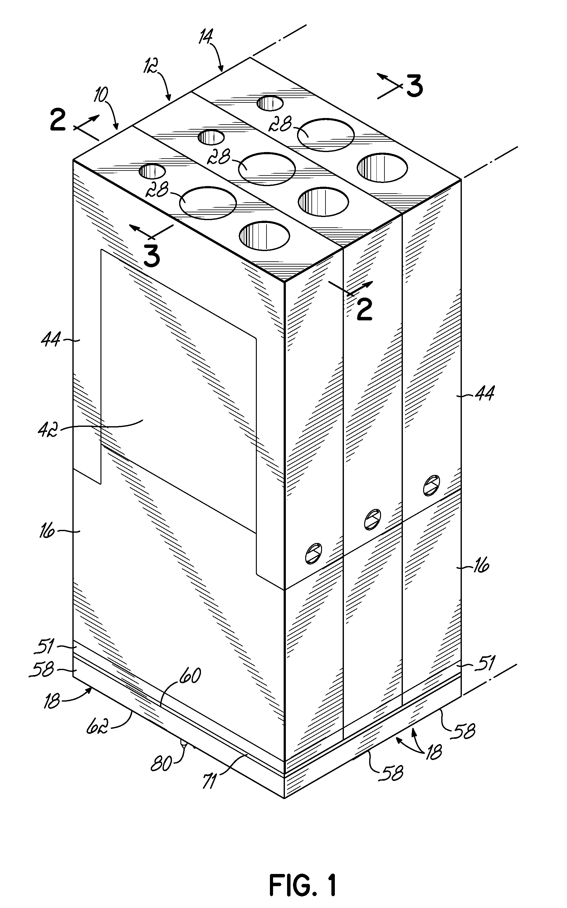
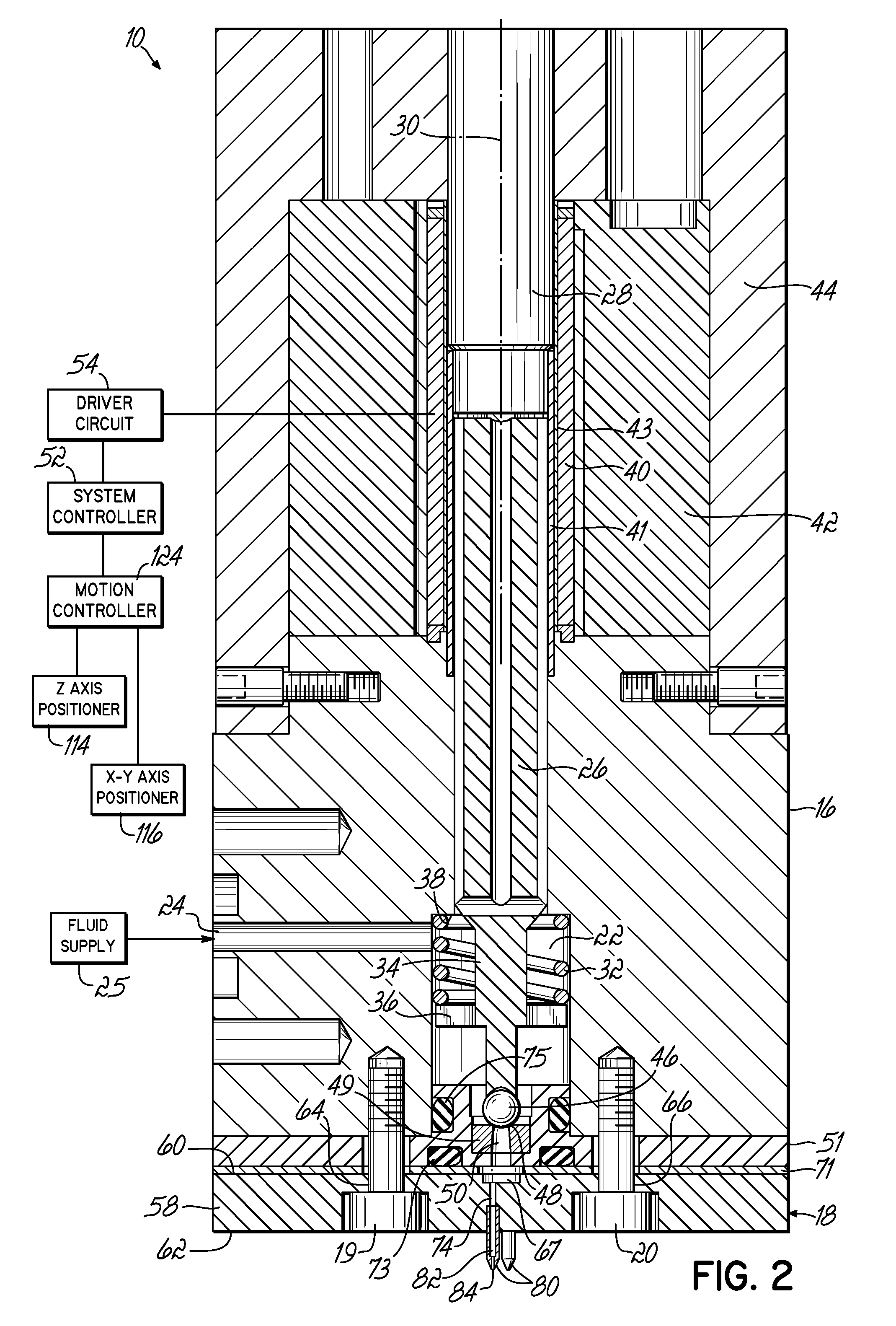
[0024]With reference to FIGS. 1-3, a plurality of fluid guns or dispensers 10, 12, 14 are configured as a single dispensing head and may be used in a fluid dispensing machine or system 110 (FIG. 6) for intermittently dispensing amounts of a viscous fluid onto a stationary substrate 120 (FIG. 6). Fluid dispensers 10, 12, 14 may be used to dispense ambient temperature viscous fluids, including cold adhesives or glues, and heated viscous liquids, such as conformal coatings, fluxes, and hot melt adhesives. The fluid dispenser 10, 12, 14 are operated in a known manner for intermittently dispensing viscous fluid in discrete volumes on the stationary substrate 120. As shown in FIG. 1, the fluid dispensers 10, 12, 14 are positioned side-by-side in a stack or juxtaposed to define the dispensing head of the fluid dispensing system 110 and are associated with a nozzle plate 18. The compactness of the fluid dispensers 10, 12, 14 and, in particular, the narrowness of the fluid dispensers 10, 12,...


PUM

PropertyMeasurementUnit
heightaaaaaaaaaa
frequencyaaaaaaaaaa
inner diameteraaaaaaaaaa

Abstract

Fluid dispensers and methods for dispensing viscous fluids with improved edge definition. Pressurized fluid is periodically supplied in pulses to nozzles in a nozzle plate of a dispensing head as the dispensing head is moved by a multi-axis stage relative to a stationary substrate. Droplets are discharged from the nozzles and impact on the substrate. The droplets coalesce together to define the coating. The discharge from one or more groups of nozzles can be temporarily suspended to avoid coating a component or area on the substrate while adjacent areas continue to receive droplets of the fluid.

Description

FIELD OF THE INVENTION[0001]The present invention relates generally to fluid dispensers for dispensing viscous fluids and, in particular, to fluid dispensers configured to dispense viscous fluids onto substrates with improved precision and edge definition.BACKGROUND OF THE INVENTION[0002]Non-contact fluid dispensers are often used to apply minute amounts of viscous materials onto substrates. For example, non-contact fluid dispensers are used to apply various viscous materials in small amounts onto electronic substrates like printed circuit boards (PCBs) or semiconductor carriers or wafers. Numerous applications exist that dispense a viscous material from a non-contact dispenser onto a substrate. In semiconductor package assembly, applications exist for underfilling, solder ball reinforcement in ball grid arrays, dam and fill operations, chip encapsulation, underfilling chip scale packages, cavity fill dispensing, die attach dispensing, lid seal dispensing, no flow underfilling, flux...

Claims


Application Information

Patent Timeline
Patent Type & Authority Applications(United States)
IPC IPC(8): B05C5/00B05D1/02
CPCB05C5/0279B05C11/1028B05C11/1034H01L2924/0002H01L2924/00H01L23/48H01L23/52
Inventor HASSLER, JR., WILLIAM L.TEDROW, JON D.
Owner NORDSON CORP
Why Eureka
Try Eureka