Pneumatic Tool

a pneumatic tool and tool attachment technology, applied in the field of pneumatic tools, can solve the problems of high air consumption, low efficiency, and low efficiency of conventional pneumatic tools, and achieve the effect of minimizing the rotation of the second piston and increasing the rotational movement (pivotal movement) of the tool attachment member

Inactive Publication Date: 2009-04-30
NITTO KOHKI CO LTD
View PDF9 Cites 13 Cited by
  • Summary
  • Abstract
  • Description
  • Claims
  • Application Information

AI Technical Summary

Benefits of technology

[0008]These pneumatic tools can be made simple in structure and light in weight in comparison to the aforementioned conventional tools. In addition, the pneumatic tools of the present invention can smoothly supply and discharge compressed air and can be driven with a low air consumption in comparison to the conventional tools.
[0013]Specifically, the pneumatic tool may be arranged as follows. The tool attachment member has a circular columnar shape as a whole. The second piston is positioned out of contact with the inner surface of the housing and engaged with the tool attachment member so as to be slidable in the direction of the axis and rotatable about the axis relative to the tool attachment member. The second urging means is a coil spring provided around the tool attachment member. To prevent rotation of the second piston about the axis, the forward end of the coil spring is connected to a spring support member secured to the housing, and the rear end of the coil spring is connected to the second piston.
[0017]In a case where the prevention of rotation of the second piston by the coil spring is not perfect, when the pin provided on the tool attachment member is guided along the guide groove to cause the tool attachment member to rotate, the second piston is urged to rotate in the opposite direction by its counteraction. Even in such a case, the radial bearing reduces the force applied to the second piston from the pin so as to urge the second piston to rotate, thus minimizing the rotation of the second piston. Consequently, the rotational movement (pivotal movement) of the tool attachment member can be increased.

Problems solved by technology

These conventional pneumatic tools suffer, however, from problems such as a complicated structure, a relatively heavy weight, and a high air consumption.
Further, supply and discharge of compressed air may fail to be smoothly performed, resulting in an interference with the operation of the tool concerned.

Method used


Image

  • Pneumatic Tool
  • Pneumatic Tool
  • Pneumatic Tool

Examples


Embodiment Construction

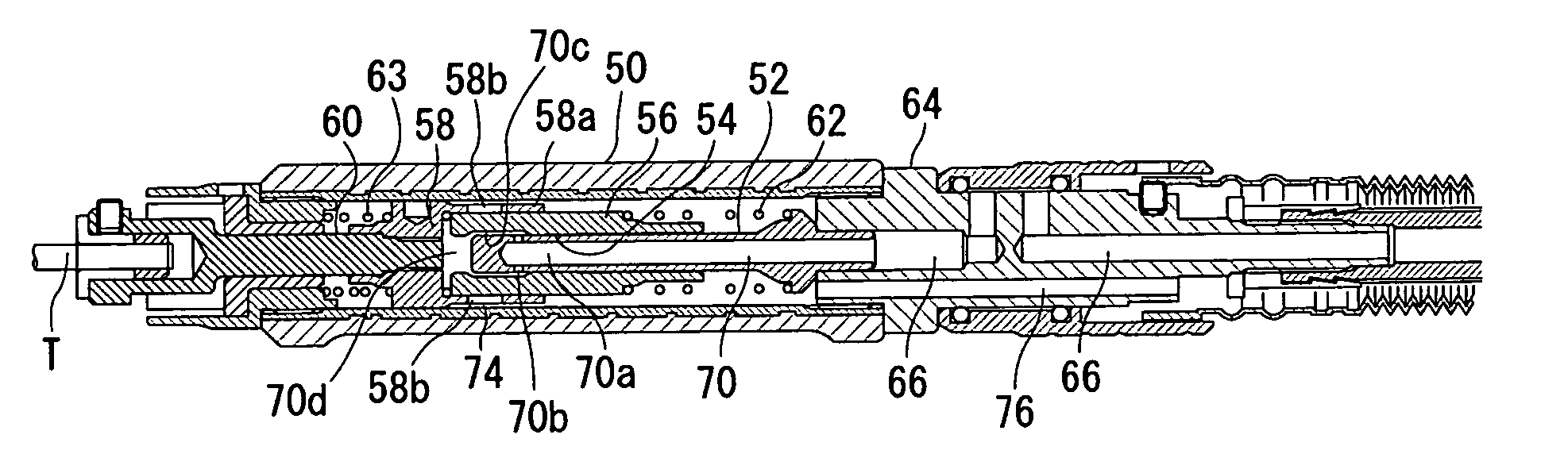
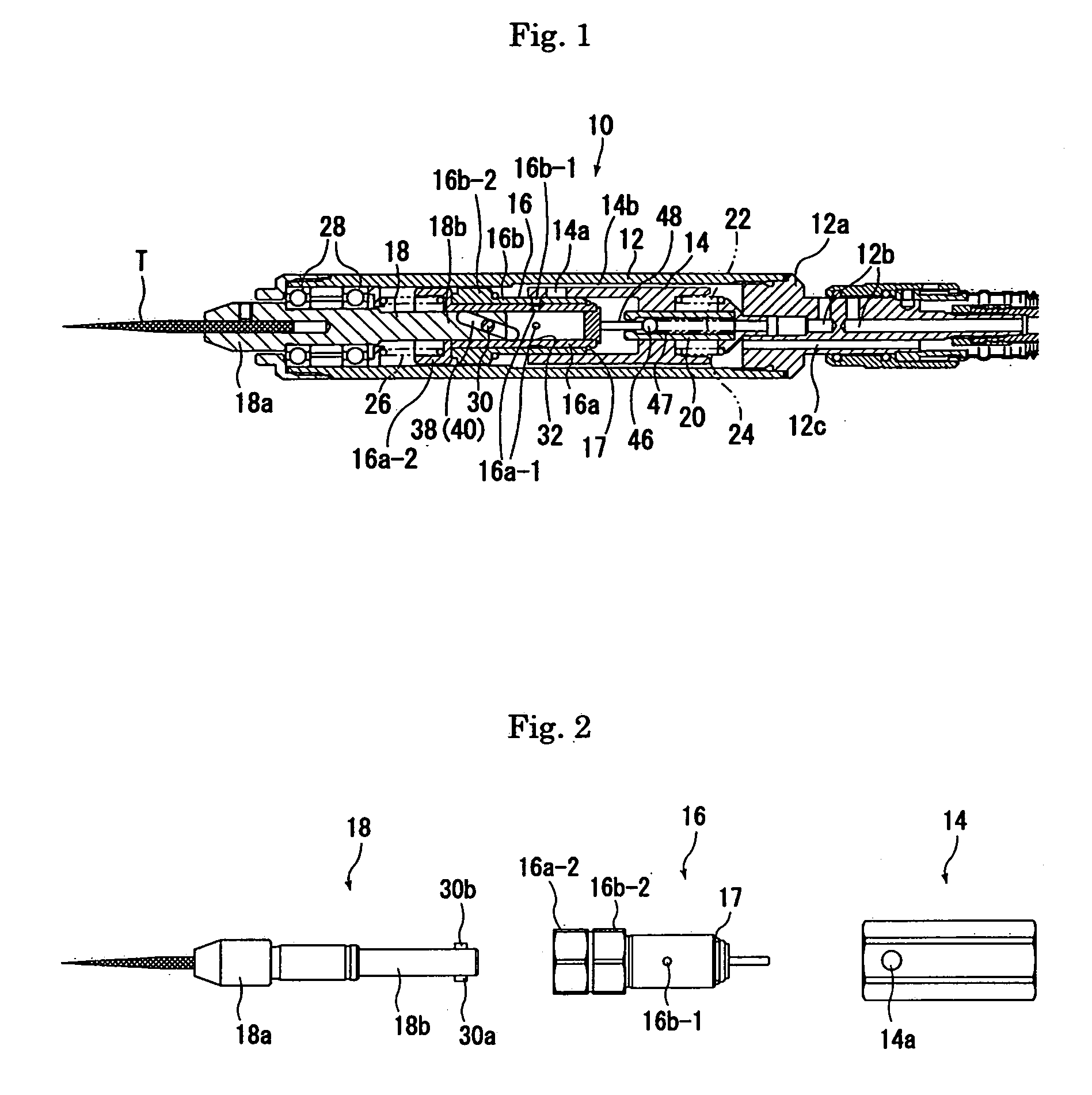
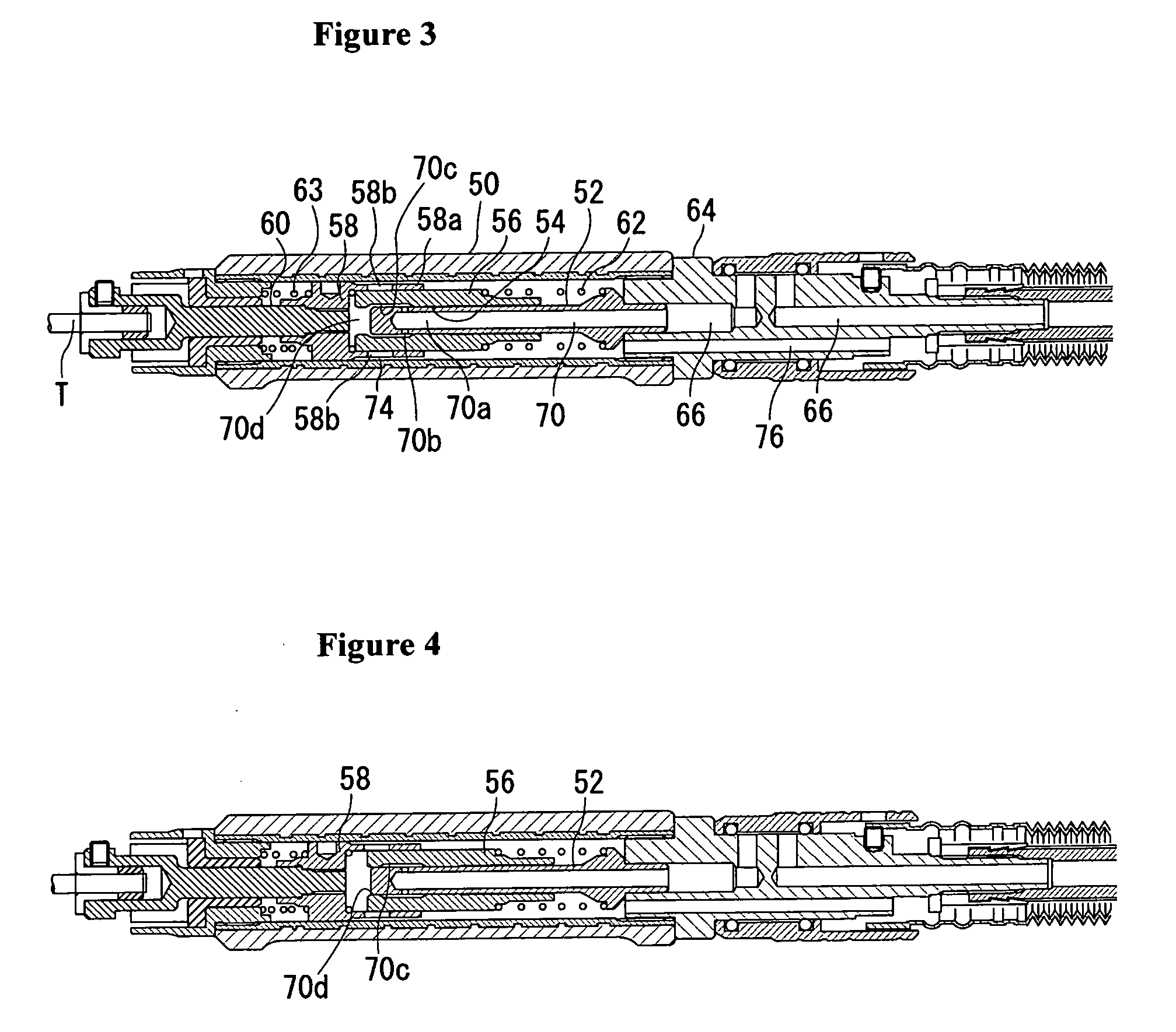
[0072]First, an embodiment in which the present invention is applied to an oscillating grinding tool will be explained in detail with reference to FIGS. 1 and 2.

[0073]FIG. 1 is a sectional side view of an oscillating grinding tool 10 according to the present invention. FIG. 2 is an exploded view illustrating the oscillating grinding tool 10, with a tubular housing 12 removed therefrom to show main elements mounted in the housing 12.

[0074]The oscillating grinding tool 10 has a tubular housing 12 and other main elements that are coaxially mounted in the housing 12, i.e. a tubular first piston 14 slidable in the axial direction of the housing 12, a second piston 16 slidable in the first piston 14, and a tool attachment oscillating member 18 drivingly connected to the second piston 16 and oscillated about the longitudinal axis thereof.

[0075]The first piston 14 is urged forward by a compression coil spring 24 set between the first piston 14 and the rear end of the housing 12. The second ...


PUM

PropertyMeasurementUnit
timeaaaaaaaaaa
distanceaaaaaaaaaa
angleaaaaaaaaaa

Abstract

The invention of this application provides a pneumatic tool with a simple structure. The tool has a tubular housing (50), a stationary shaft (52), a first piston (56) slidable along the stationary shaft, a second piston (58), a tool attachment member (60) drivingly connected to the second piston, a compressed air supply path (70) extending through the stationary shaft to supply compressed air between the first and second pistons, and an air discharge path (76) for discharging the compressed air supplied between the first and second pistons to the outside of the housing when the first and second pistons are separated by a predetermined distance. The compressed air supply path has an axial portion (70a) in the stationary shaft and a radial portion (70b), a compressed air inlet recess (70c) in the inner wall surface of a shaft sliding hole, and a supply outlet (70d) extending forward from the forward end of the compressed air inlet recess and communicating with a portion between the first and second pistons.

Description

TECHNICAL FIELD[0001]The present invention relates to pneumatic tools such as reciprocating tools, e.g. a hand-held saw reciprocatively driven by compressed air, and pneumatic rotary tools, e.g. a hand-held grinding tool driven to oscillate by compressed air.BACKGROUND ART[0002]There have heretofore been developed pneumatic tools having various structures (for example, see Patent Documents 1 and 2).[0003]These conventional pneumatic tools suffer, however, from problems such as a complicated structure, a relatively heavy weight, and a high air consumption. Further, supply and discharge of compressed air may fail to be smoothly performed, resulting in an interference with the operation of the tool concerned.Patent Document 1: Japanese Examined Utility Model Application Publication No. Hei 4-2781Patent Document 2: U.S. Pat. No. 5,755,292DISCLOSURE OF THE INVENTIONProblem to be Solved by the Invention[0004]The present invention has been made in view of the above-described circumstances,...

Claims


Application Information

Patent Timeline
Patent Type & Authority Applications(United States)
IPC IPC(8): B23Q5/033B23D51/18
CPCB24B23/043B23D51/18B25F5/00
Inventor SHIBUYA, KUNIAKIYAMAGUCHI, MUNENORISUZUKI, YASUMASANAKAJOH, TAKASHI
Owner NITTO KOHKI CO LTD
Why Eureka
Try Eureka