Supercharge Your Innovation With Domain-Expert AI Agents!

Printed interconnection board and method of manufacturing the same

a technology of interconnection board and printed board, which is applied in the direction of printed circuit, printed circuit manufacturing, printed circuit aspects, etc., can solve the problems of failure to achieve mounting reliability, electrically conductive carbon powder may fall off, and exfoliation occurs, so as to prevent the exfoliation of a cfrp layer, the effect of high thermal conductivity and low thermal expansivity

Active Publication Date: 2009-04-30
MITSUBISHI ELECTRIC CORP
View PDF6 Cites 19 Cited by
  • Summary
  • Abstract
  • Description
  • Claims
  • Application Information

AI Technical Summary

Benefits of technology

[0010]The present invention has been made in view of the above problem, and one object of the present invention is to provide a printed interconnection board with low thermal expansivity and high thermal conductivity capable of preventing exfoliation of a CFRP layer on a side surface of a substrate using CFRP as a core, as well as preventing falling-off of carbon powders from the CFRP layer, and a method of manufacturing the same.
[0014]According to the present invention, the coating layer coats the outer peripheral edge of the core as seen in a plan view, and thus falling-off of carbon powders from the core including carbon fiber reinforced plastic can be prevented, causing no exfoliation of a carbon fiber reinforced plastic layer in a heat cycle test. Therefore, insulation reliability and heat cycle reliability can be enhanced.

Problems solved by technology

However, aluminum has a high coefficient of thermal expansion of approximately 24 ppm / ° C., whereas a ceramic component has a low coefficient of thermal expansion of approximately 7 ppm / ° C. Therefore, there arises a problem that when a heat cycle test is conducted, a crack occurs at a solder joint portion due to a difference in the coefficients of thermal expansion of aluminum and the ceramic component, failing to achieve mounting reliability.
However, there has been a problem that, in a substrate using CFRP prepared by laminating prepregs including unidirectional carbon fiber at angles of 0°, 90°, 90°, and 0° as a core material, exfoliation occurs in a CFRP layer on a side surface of the substrate in a heat cycle test.
Further, since the CFRP layer is exposed on the side surface of the substrate, there has been a risk that electrically conductive carbon powders may fall off, adhere to between interconnections of the substrate or an insulating portion of a device, and cause a short circuit between the interconnections.
In particular, when exfoliation occurs in the CFRP layer at an end portion of the substrate in a heat cycle test, falling-off of carbon powders has exerted a significant effect at an unacceptable level.

Method used


Image

  • Printed interconnection board and method of manufacturing the same
  • Printed interconnection board and method of manufacturing the same
  • Printed interconnection board and method of manufacturing the same

Examples


first embodiment

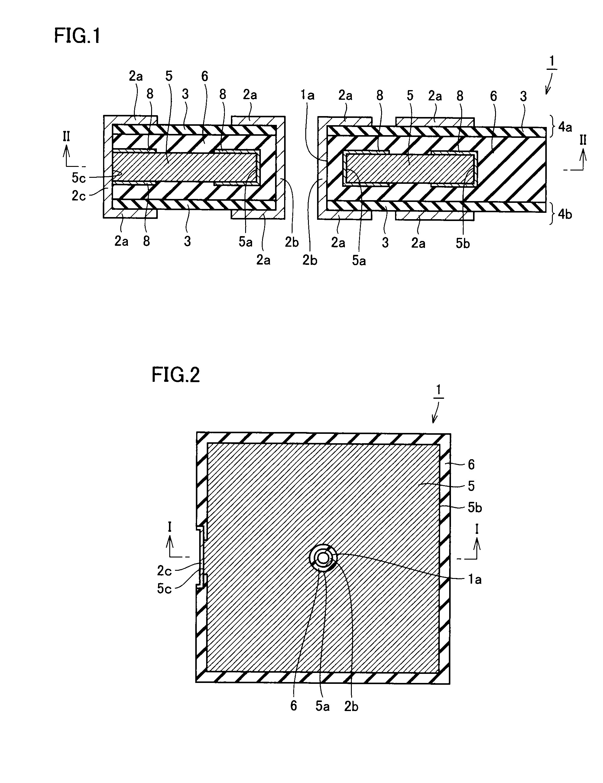
[0030]A cross sectional portion taken along a line I-I of FIG. 2 corresponds to a cross section of FIG. 1. Further, in FIG. 2, an electrically conductive layer 8 is not illustrated for the sake of convenience of description.

[0031]Referring to FIG. 1, a printed interconnection board 1 mainly has a pair of upper and lower signal circuit layers 4a and 4b, a core including a CFRP layer 5 (hereinafter referred to as a CFRP core), an adhesive member 6, a first electrically conductive layer 2b, and coating layers 2c and 6.

[0032]Each of the pair of upper and lower signal circuit layers 4a and 4b has an insulating base material 3, and a signal interconnection 2a formed on a surface of insulating base material 3. Insulating base material 3 is, for example, a material prepared by curing a prepreg produced by impregnating glass cloth with epoxy resin or the like, and preferably has low thermal expansivity comparable to that of CFRP layer 5 to reduce stress caused by a difference in coefficients...

second embodiment

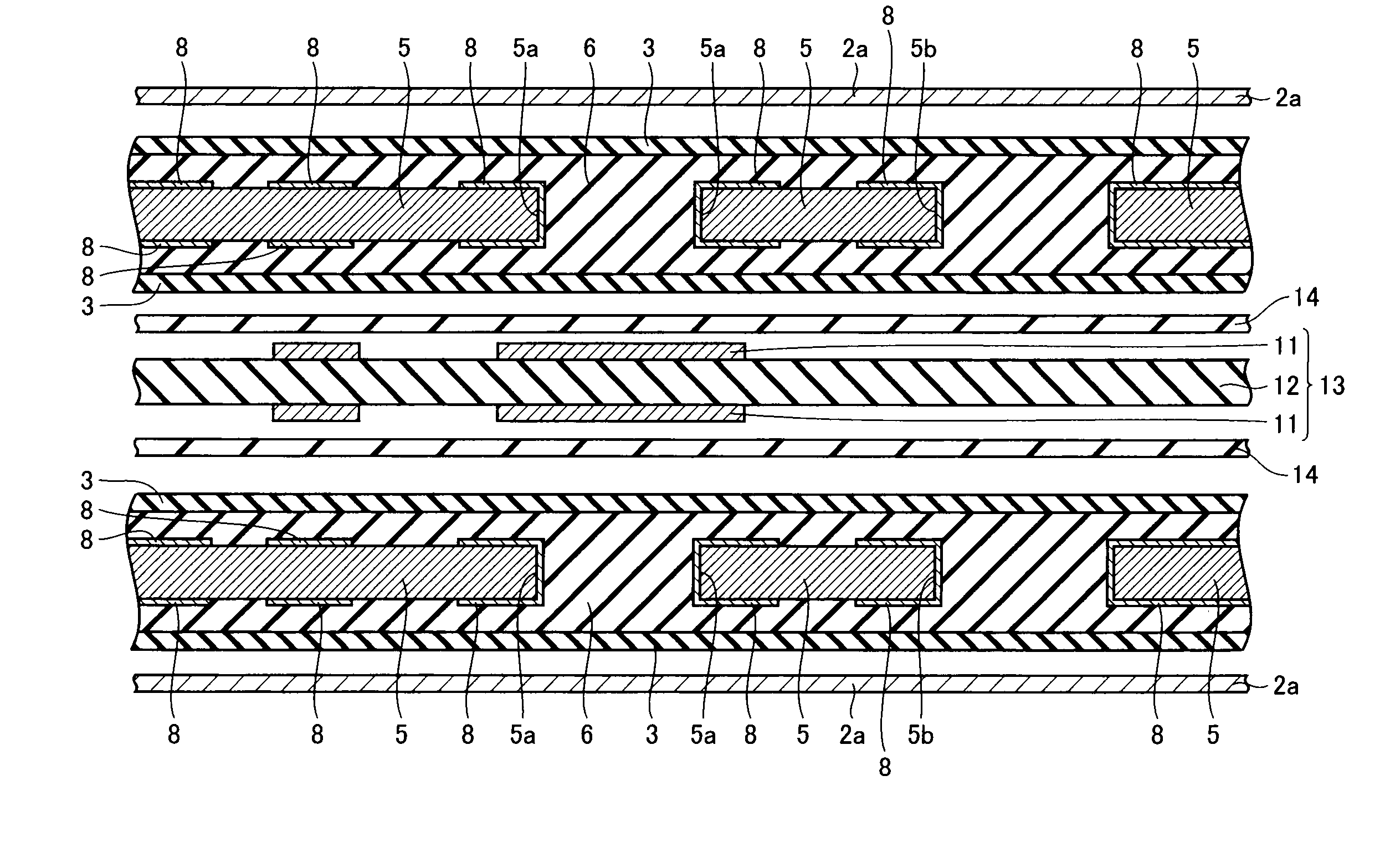
[0073]In the first embodiment, the description has been given of a case where a laminated board 10 shown in FIG. 8 is formed, and thereafter copper foil 2a is placed and laminated above and below the laminated board as shown in FIG. 9. In contrast, in the present embodiment, a four-layered printed interconnection board is manufactured using laminated board 10 shown in FIG. 8. Hereinafter, a description thereof will be given. Referring to FIG. 21, two laminated boards 10 shown in FIG. 8 are prepared. An internal layer signal circuit layer 13 is arranged between these two laminated boards 10 with glass epoxy prepregs 14 interposed between internal layer signal circuit layer 13 and laminated boards 10, and electrically conductive layers 2a made of, for example, copper foil are arranged on the two laminated boards 10 on sides opposite to internal layer signal circuit layer 13. With this arrangement, heat and pressure are applied using, for example, vacuum pressing. Thereafter, manufactu...

first example

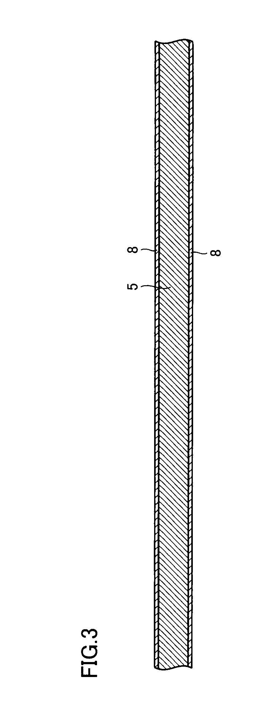
[0081]Firstly, a CFRP core (thickness: 0.35 mm, size: 340 mm×250 mm) having prepreg 5 (CFRP layer 5) including carbon fiber (a cross material) with a thermal conductivity of 500 W / m·K, and 18 μm-thick copper foil 8 laminated on prepreg 5 was prepared (see FIG. 3).

[0082]Next, holes were drilled in the CFRP core to provide primary through hole 5a with a diameter of 1.5 mm and primary through hole 5b as an elongated hole with a width of 4 mm (see FIG. 4). On this occasion, carbon powders were dispersed from the wall surfaces of primary through holes 5a and 5b. Subsequently, copper plating was performed (see FIG. 5). Thereby, copper plating 8 was formed on the both wall surfaces of primary through holes 5a and 5b, preventing dispersion of carbon powders from the wall surfaces.

[0083]Next, an unnecessary portion of copper 8 was removed by patterning (see FIG. 6). Thereby, copper was removed from the surface of CFRP layer 5, and the surface of CFRP layer 5 was exposed. However, on the surf...


PUM

PropertyMeasurementUnit
thermal conductivityaaaaaaaaaa
temperatureaaaaaaaaaa
thermal conductivityaaaaaaaaaa

Abstract

A CFRP core including a CFRP layer has a primary through hole. An adhesive member coats a wall surface of the primary through hole, and has a secondary through hole extending within the primary through hole. An electrically conductive layer is formed on a wall surface of the secondary through hole for electrically connecting upper and lower signal interconnections via the secondary through hole. A coating layer coats an outer peripheral edge of the CFRP core as seen in a plan view. Thereby, a printed interconnection board with low thermal expansivity and high thermal conductivity capable of preventing exfoliation of a CFRP layer on a side surface of a substrate using CFRP as a core, as well as preventing falling-off of carbon powders from the CFRP layer, and a method of manufacturing the same can be obtained.

Description

BACKGROUND OF THE INVENTION[0001]1. Field of the Invention[0002]The present invention relates to a printed interconnection board and a method of manufacturing the same, and in particular, to a printed interconnection board having a core including carbon fiber reinforced plastic and a method of manufacturing the same.[0003]2. Description of the Background Art[0004]In recent years, it has become desirable for printed interconnection boards to include a substrate with an excellent heat dissipation property, as electronic components are mounted in higher density. A metal core substrate has been known as a printed interconnection board excellent in heat dissipation property, and has already been put to practical use. The metal core substrate uses a metal having high thermal conductivity, such as aluminum (Al), copper (Cu), or the like, as a core material, and thereby can dissipate heat from a heat-generating component throughout the substrate and suppress an increase in the temperature o...

Claims


Application Information

Patent Timeline
Patent Type & Authority Applications(United States)
IPC IPC(8): H05K1/00H05K3/00
CPCH05K1/0366Y10T29/49124H05K3/403H05K3/429H05K3/445H05K3/4626H05K3/4641H05K3/4652H05K3/4655H05K2201/0195H05K2201/0323H05K2201/0347H05K2201/09181H05K2201/09809H05K3/0052
Inventor SAMEJIMA, SOHEISATO, SADAOOZAKI, TSUYOSHIOSUGA, HIROYUKIKUMADA, TERUHIKO
Owner MITSUBISHI ELECTRIC CORP
Features
  • R&D
  • Intellectual Property
  • Life Sciences
  • Materials
  • Tech Scout
  • Unparalleled Data Quality
  • Higher Quality Content
  • 60% Fewer Hallucinations
Learn More