Motor rotation angle detection device

a detection device and motor technology, applied in the direction of electrical steering, instruments, transportation and packaging, etc., can solve the problems of reducing the accuracy of the resolver in detecting the rotation angle, and affecting the accuracy of the resolver. , to achieve the effect of high accuracy

Inactive Publication Date: 2009-04-30
HONDA MOTOR CO LTD
View PDF8 Cites 11 Cited by
  • Summary
  • Abstract
  • Description
  • Claims
  • Application Information

AI Technical Summary

Benefits of technology

[0008]The present invention has been made in view of the above circumstances, and it is an object of the present invention to prevent the rotor of the resolver from being distorted, and thus to detect the rotation angle of the motor with high accuracy.
[0010]With the configuration according to the first feature and aspect of the present invention, when the rotation angle of the motor for generating the assist torque for steering the wheels is detected by use of the resolver configured by arranging the outer circumferential surface of the annular rotor inside the inner circumferential surface of the annular stator with the air gap interposed in between so that the rotor and the stator are rotatable relative to each other, it is possible to stabilize the magnetic permeability of the rotor, and accordingly to increase the accuracy with which the resolver detects the rotation angle of the motor. This happens because the rotor supporting member is connected to the rotary shaft of the motor, and because the rotor of the resolver is extended out from the axial end portion of the rotor supporting member so as to surround the outer periphery of the rotary shaft of the motor. Thereby, neither the load which occurs due to press-fitting when the rotor supporting member is connected to the rotary shaft nor the load which occurs due to torsional load acting on the rotary shaft as a result of a torque of the motor is transmitted to the rotor.
[0014]With the configuration according to the third feature and aspect of the present invention, the rotary shaft of the motor is connected to the input shaft of the decelerator by use of the Oldham coupling. For this reason, an imbalanced load is prevented from being applied to the rotary shaft by causing the Oldham coupling to absorb any misalignment between the axis of the rotary shaft of the motor and the axis of the input shaft of the decelerator. Thereby, distortion of the rotor of the resolver can be further reduced to further increase the detection accuracy.
[0016]With the configuration according to the fourth feature and aspect of the present invention, the rotary shaft of the motor is connected to the coupling by press-fit. This makes it easy to connect the rotary shaft and the coupling together. Although, on the other hand, the coupling is elastically deformed in a way that the diameter of the coupling is enlarged, the distortion of the resolver rotor can be reduced because the rotor extends from an axial end portion of the coupling so as to surround the outer periphery of the rotary shaft. Thereby, the detection accuracy can be increased.

Problems solved by technology

However, problems arise in using a resolver such as that disclosed in JP 2005-247079.
This lower magnetic permeability leads to reduction in the accuracy of the resolver in detecting the rotation angle.
Moreover, when a distortion torque is applied to the rotary shaft of the assist motor, a stress is generated by the distortion torque, thus decreasing the magnetic permeability.
This decrease in the magnetic permeability reduces the accuracy of the resolver in detecting the rotation angle.

Method used


Image

  • Motor rotation angle detection device
  • Motor rotation angle detection device
  • Motor rotation angle detection device

Examples


Embodiment Construction

[0030]A first exemplary embodiment of the present invention will be described based on FIGS. 1 to 6.

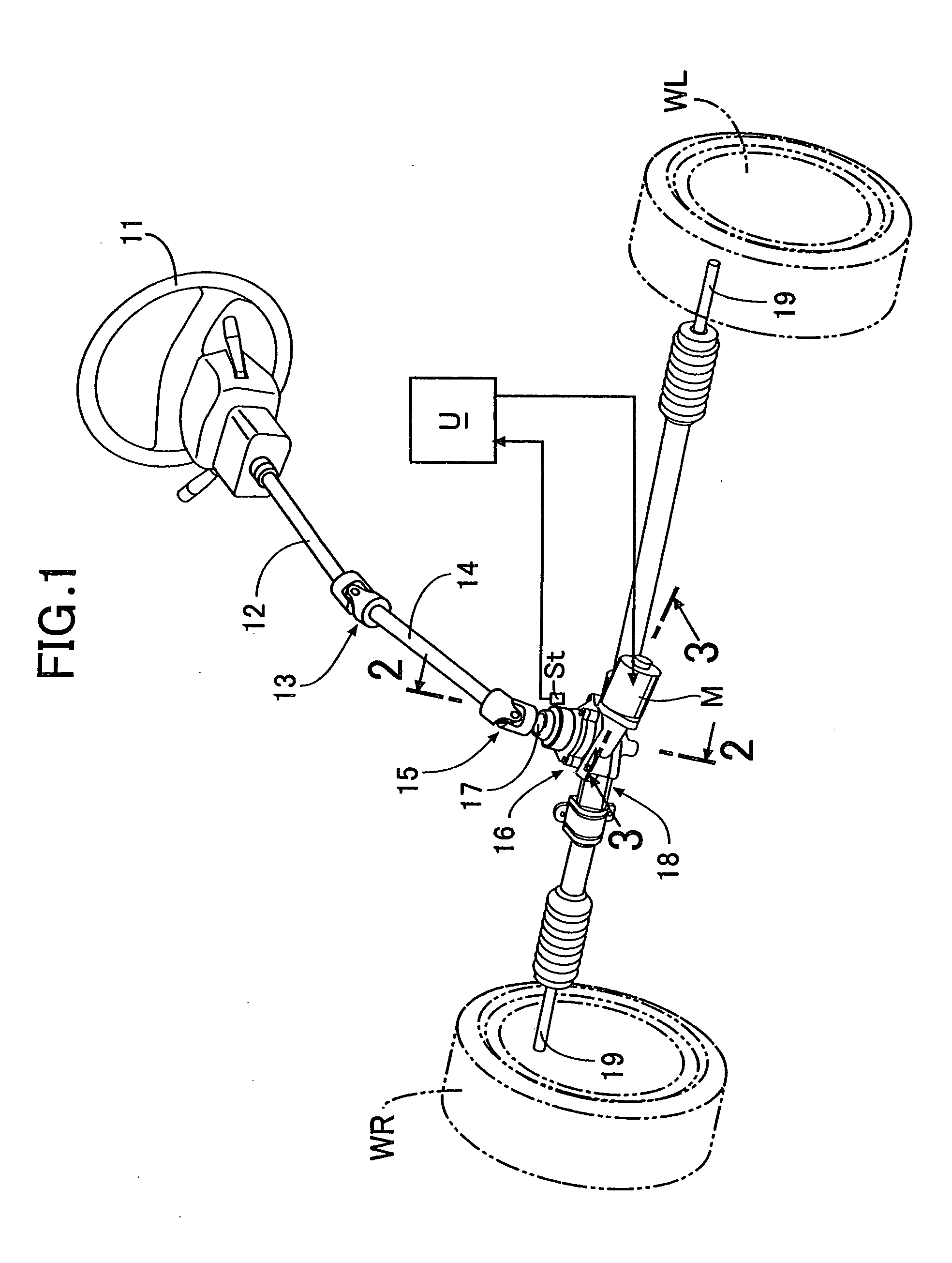
[0031]As shown in FIG. 1, an upper steering shaft 12, designed to rotate together with a steering wheel 11, is connected to a pinion shaft 17 protruding from a decelerator or reduction gear 16 via an upper universal joint 13, a lower steering shaft 14 and a lower universal joint 15. Tie rods 19, 19 protruding from left and right ends of a steering gear box 18 connected to the bottom tip of the decelerator or reduction gear 16 are connected to unillustrated knuckles of the left and right road wheels WL, WR. An assist motor M, configured of a DC brushless motor, is supported by the decelerator or reduction gear 16. The operation of this assist motor M is controlled by an electronic control unit U into which a signal is inputted from a steering torque detecting device St housed in the decelerator or reduction gear 16.

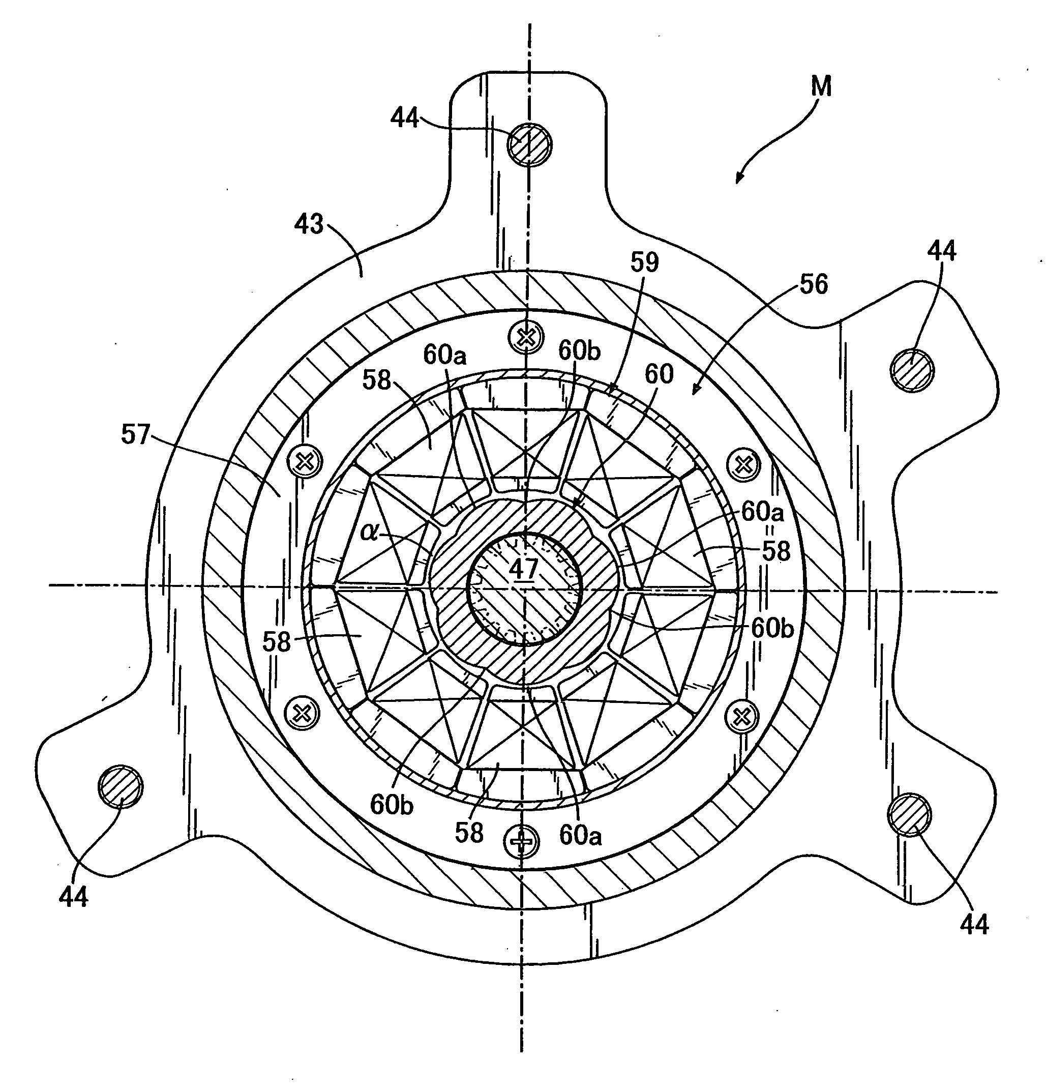
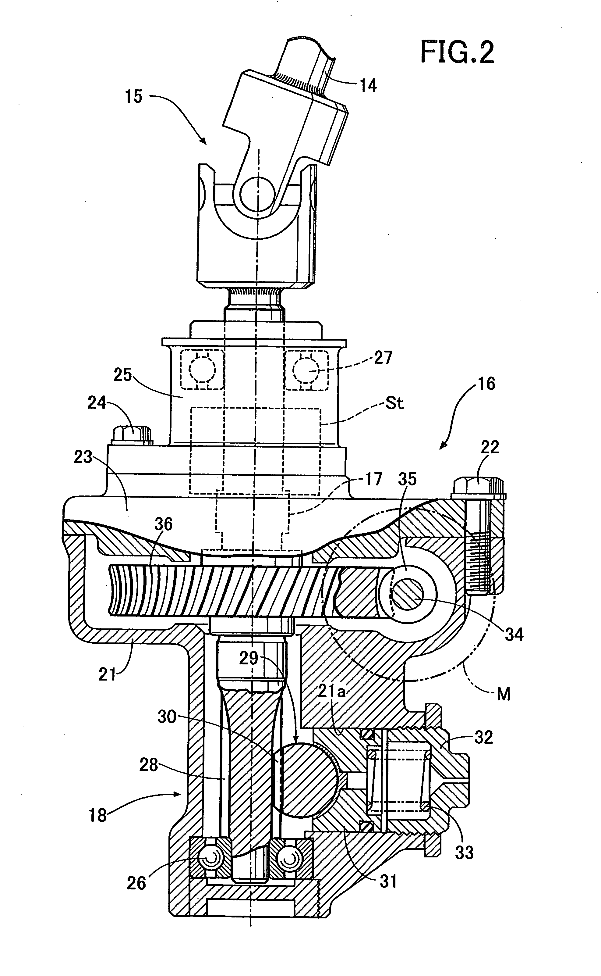
[0032]As shown in FIG. 2, the decelerator 16 includes: a lower housing ...


PUM


Abstract

A motor rotation angle detection device, comprising a resolver which detects a rotation angle of a motor generating an assist torque for steering road wheels. The resolver includes an annular rotor disposed inside an annular stator with an air gap interposed in between an outer circumferential surface of the rotor and an inner circumferential surface of the stator, so that the stator and the rotor are rotatable relative to each other, wherein a rotor supporting member is connected to a rotary shaft of the motor, and the rotor extends out from an axial end portion of the rotor supporting member so as to surround an outer periphery of the rotary shaft. With the such a motor rotation angle detection device, it is possible to stabilize the magnetic permeability of the rotor, and accordingly to increase an accuracy with which the rotation angle of the motor is detected.

Description

CROSS-REFERENCE TO RELATED APPLICATIONS[0001]The present invention claims priority under 35 USC §119 based on Japanese patent application No. 2007-277179 filed 25 Oct. 2007. The subject matter of this priority document is incorporated by reference herein.BACKGROUND OF THE INVENTION[0002]1. Field of the Invention[0003]The present invention relates to a motor rotation angle detection device, for detecting, using a resolver, a rotation angle of a motor generating an assist torque for steering road wheels, wherein the resolver is configured by arranging an outer circumferential surface of an annular rotor inside an inner circumferential surface of an annular stator with an air gap interposed in between, so that the stator and the rotor are rotatable relative to each other.[0004]2. Description of the Related Art[0005]Japanese Patent Application Laid-open No. 2005-247079 has made publicly-known an electric power steering system for assisting the steering operation of a driver by use of a ...

Claims


Application Information

Patent Timeline
Patent Type & Authority Applications(United States)
IPC IPC(8): B62D5/04G01B7/30
CPCB62D5/0409H02K29/12B62D15/0235
Inventor MIYOSHI, TAKASHIYONEDA, ATSUHIKOSHIMIZU, YASUO
Owner HONDA MOTOR CO LTD
Why Eureka
Try Eureka