Connecting structure for connecting electrical apparatus and feeder terminal portion, and vehicle

a technology for connecting structures and electrical equipment, applied in the direction of electrical devices, coupling device connections, transportation and packaging, etc., can solve the problems of increasing manufacturing costs, difficult difficulty in attachment work for flexible members, so as to facilitate attachment work, simplify the structure of connecting parts, and simplify the effect of the structure of the connecting portion

Inactive Publication Date: 2009-04-30
TOYOTA JIDOSHA KK
View PDF7 Cites 28 Cited by
  • Summary
  • Abstract
  • Description
  • Claims
  • Application Information

AI Technical Summary

Benefits of technology

[0009]An object of the present invention is to provide a connecting structure for connecting an electrical apparatus and a feeder terminal portion, which can facilitate connecting work, simplify a structure of a connecting portion as well, and furthermore, suppress manufacturing cost increase, even if an amount of misalignment between a led-out conductor portion of the electrical apparatus and the feeder terminal portion and its variations are increased, and a vehicle equipped with the connecting structure.
[0011]The electrical apparatus is, for example, a rotating electrical machine. A coating layer may be formed at a surface of the led-out conductor portion to improve stiffness of the led-out conductor portion. The feeder terminal portion may be a feeding terminal block.
[0021]In the connecting structure for connecting the electrical apparatus and the feeder terminal portion in the present invention, the connecting member has the misalignment absorbing portion, and hence even if an amount of relative misalignment between the led-out conductor portion of the electrical apparatus and the feeder terminal portion and its variations are large, the misalignment absorbing portion can preferentially be deformed to absorb the amount of misalignment between the led-out conductor portion of the electrical apparatus and the feeder terminal portion, to thereby facilitate attachment work for the connecting member. Further, it is possible to provide the misalignment absorbing portion only by shaping a part of the connecting member in a bent manner, so that a structure of the connecting member may also be simplified. As a result, it becomes possible to simplify a structure of the connecting portion for connecting the led-out conductor portion of the electrical apparatus and the feeder terminal portion, and even suppress manufacturing cost increase.

Problems solved by technology

However, if an amount of misalignment between the led-out portion of motor winding 116 and terminal block 120 and its variations are increased, there arises a problem of difficulty in attachment work for flexible member 140.
However, wire-connecting member 130 has a complicated structure that includes a fixed terminal 132 and a movable terminal 135, and hence a structure of the connecting portion between motor winding 116 and terminal block 120 becomes complicated, resulting in a problem of manufacturing cost increase.
However, if an amount of misalignment between the led-out portion of motor winding 116 and terminal block 120 and its variations are increased, attachment work for the flexible member becomes difficult.
Further, if the above-described flexible bus bar 140 is provided at the led-out portion of motor winding 116, a problem of manufacturing cost increase may also arise.
Moreover, if spring-like conductor 140# having spring-like portion 141 is used as the flexible member, there may also arise a problem of increase in complexity of a structure of the flexible member.
As described above, in a connecting structure for connecting a motor winding and a terminal block in the conventional motor module mounted on a vehicle, if an amount of misalignment between the led-out portion of the motor winding and the terminal block and its variations are increased, there may arise a problem of difficulty in attachment work, a problem of increase in complexity of a structure of the connecting portion, and a problem of manufacturing cost increase.
These problems may also arise in a connecting structure that connects a led-out conductor portion of an electrical apparatus other than the motor described in each of the above-described documents, and a feeder terminal portion.

Method used


Image

  • Connecting structure for connecting electrical apparatus and feeder terminal portion, and vehicle
  • Connecting structure for connecting electrical apparatus and feeder terminal portion, and vehicle
  • Connecting structure for connecting electrical apparatus and feeder terminal portion, and vehicle

Examples


first embodiment

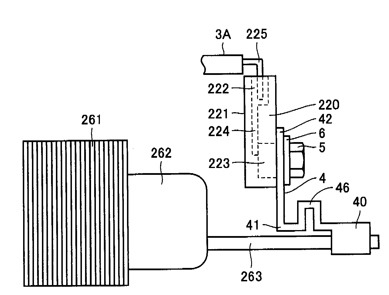
[0051]Next, a first embodiment of the present invention will be described with the use of FIG. 3 to FIG. 5. FIG. 3 is a drawing that shows a connecting structure for connecting bus bar (led-out conductor portion) 263 of the motor generator and feeding terminal block 220 serving as the feeder terminal portion, in the first embodiment. The connecting structure shown in FIG. 3 is identified as a structure useful for an FR layout hybrid vehicle.

[0052]As shown in FIG. 3, bus bar 263 led out from coil end 262 of stator core 261 extends in an axial direction of the stator of the motor generator. In the first embodiment, a surface of bus bar 263 is varnished to improve stiffness of bus bar 263. It is noted that processing other than varnishing may be applied to form a coating layer that improves stiffness of bus bar 263.

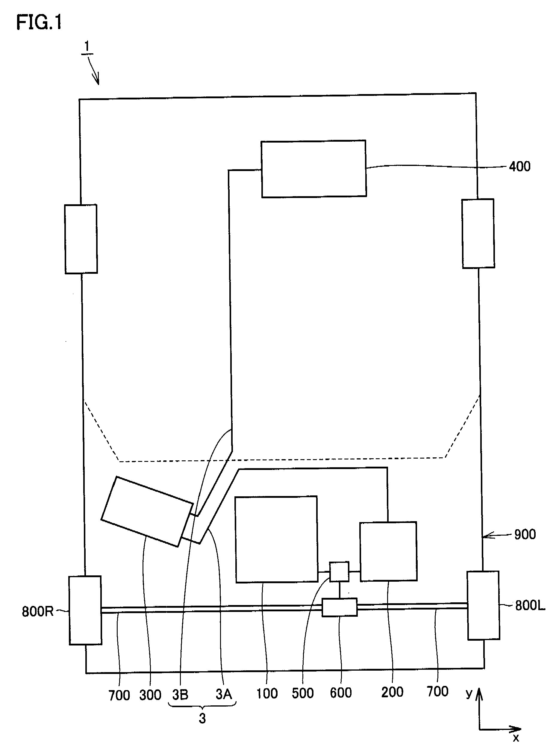
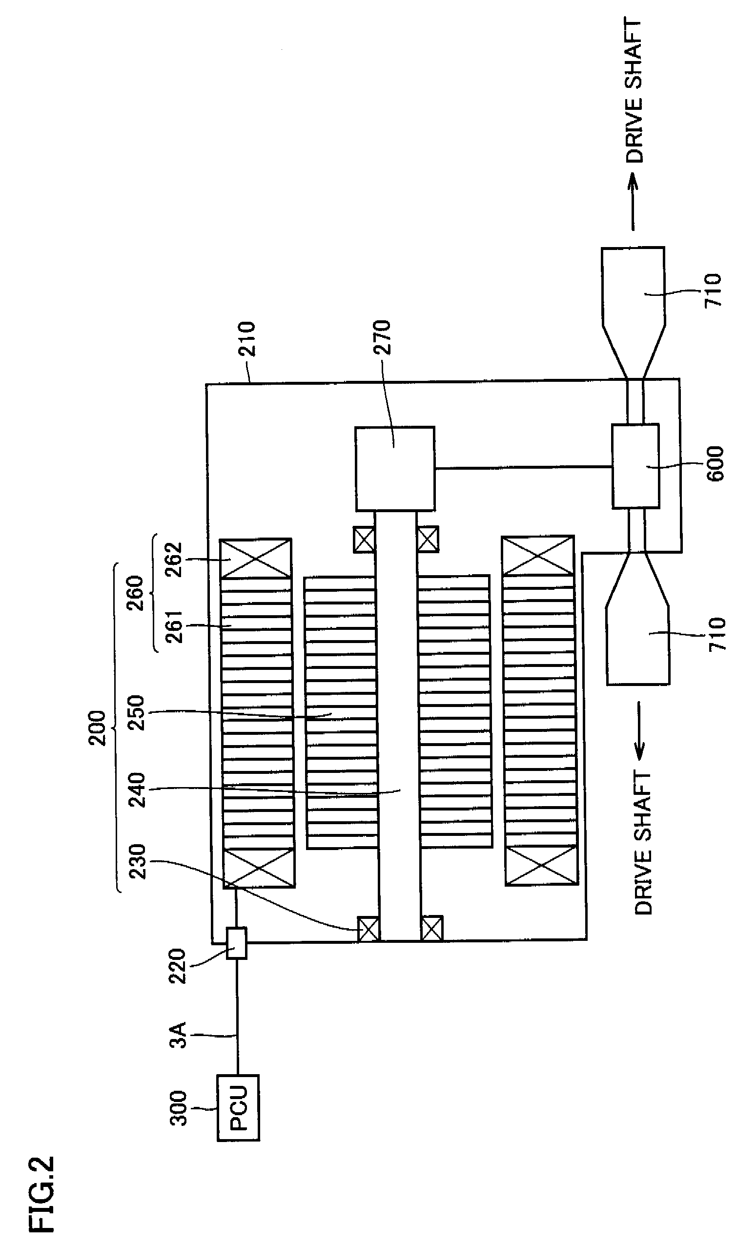
[0053]As shown in FIG. 1 and FIG. 2, for example, feeding terminal block 220 is electrically connected to electrical power supply sources such as PCU 300 and battery 400 via...

second embodiment

[0073]Next, with the use of FIG. 6 to FIG. 8, a second embodiment of the present invention and its modifications will be described. FIG. 6 is a drawing that shows a connecting structure for connecting bus bar 263 of the motor generator and feeding terminal block 220 in the second embodiment. The connecting structure in the second embodiment is also identified as a structure useful for an FR layout hybrid vehicle.

[0074]As shown in FIG. 6, in the second embodiment, a corner portion of misalignment absorbing portion 46 is rounded. By rounding the corner portion of misalignment absorbing portion 46 as such, it is possible to relieve stress concentration at the corner portion when misalignment absorbing portion 46 is deformed. Other configurations are basically similar to those of the first embodiment. Therefore, effects similar to those of the first embodiment can also be expected.

[0075]Next, with the use of FIG. 7 and FIG. 8, modifications of the second embodiment will be described. As...

third embodiment

[0078]Next, with the use ofFIG. 9, a third embodiment of the present invention will be described. FIG. 9 is a drawing that shows a connecting structure for connecting bus bar 263 of the motor generator and feeding terminal block 220 in the third embodiment. The connecting structure in the third embodiment is also identified as a structure useful for an FR layout hybrid vehicle.

[0079]In each of the embodiments described above, misalignment absorbing portion 46 has an approximately U-shape. However, the shape of misalignment absorbing portion 46 can arbitrarily be selected. As shown in FIG. 9, for example, misalignment absorbing portion 46 may have an approximately V-shape. Other configurations are basically similar to those of the first embodiment. Therefore, in the third embodiment as well, effects similar to those of the first embodiment can be expected.


PUM


Abstract

A bus bar (263) identified as a led-out conductor portion led out from a coil end (262) of a motor generator identified as an electrical apparatus, and a feeding terminal block (220) disposed at a spacing from the bus bar (263) and having a cable (3A) connected thereto, are connected by a connecting member (4). The connecting member (4) has a bent shape as a whole, and includes a misalignment absorbing portion (46) which is provided by bending a part of the connecting member (4) and is deformable to absorb misalignment between the bus bar (263) and the feeding terminal block (220).

Description

TECHNICAL FIELD[0001]The present invention relates to a connecting structure for connecting an electrical apparatus and a feeder terminal portion, and a vehicle, and particularly relates to a connecting structure between a led-out conductor portion led out from an electrical apparatus and a feeder terminal portion, and a vehicle equipped with the connecting structure.BACKGROUND ART[0002]There are various types of electrical apparatuses, and a motor is widely known as one example thereof. Motors are used for infinitely various purposes, and used in various apparatuses such as an industrial apparatus, various types of vehicles, an air-conditioning apparatus, and an environmental protection apparatus.[0003]The above-described vehicles include a hybrid vehicle and an electric vehicle, and a motor is also mounted on the hybrid vehicle and others. For example, if a motor is mounted on a hybrid vehicle, it is accommodated in an enclosure, and its coil winding is often led out to an outside...

Claims


Application Information

Patent Timeline
Patent Type & Authority Applications(United States)
IPC IPC(8): H02K3/50
CPCH01R11/05B60L3/0061H01R2201/26H01R13/6315
Inventor MIURA, TETSUYA
Owner TOYOTA JIDOSHA KK
Why Eureka
Try Eureka