Rotary apparatus

a rotary apparatus and rotary technology, applied in the direction of machines/engines, magnetic circuit rotating parts, magnetic circuit shape/form/construction, etc., can solve the problem of restricting the permissible rotating speed, and achieve the effect of preventing displacement reducing deformation and preventing the breakage of the motor end ring

Inactive Publication Date: 2009-04-30
EBARA CORP
View PDF9 Cites 5 Cited by
  • Summary
  • Abstract
  • Description
  • Claims
  • Application Information

AI Technical Summary

Benefits of technology

[0023]The use of such a tapered cross-sectional shape can reduce deformation of the motor end ring caused by its rotation.
[0024]According to the present invention, the provision to the rotor shaft of the member that covers the motor end ring makes ...

Problems solved by technology

It is possible that the strength of a motor end ring can restrict t...

Method used


Image

  • Rotary apparatus
  • Rotary apparatus
  • Rotary apparatus

Examples


Embodiment Construction

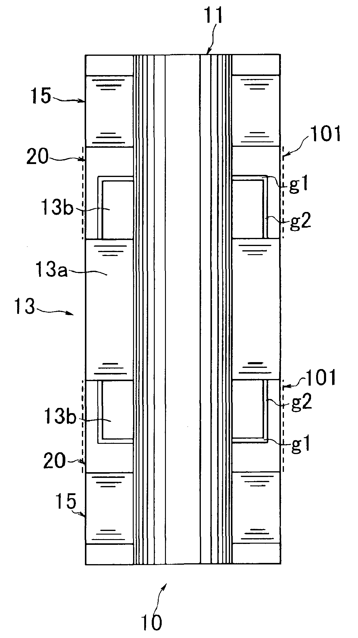
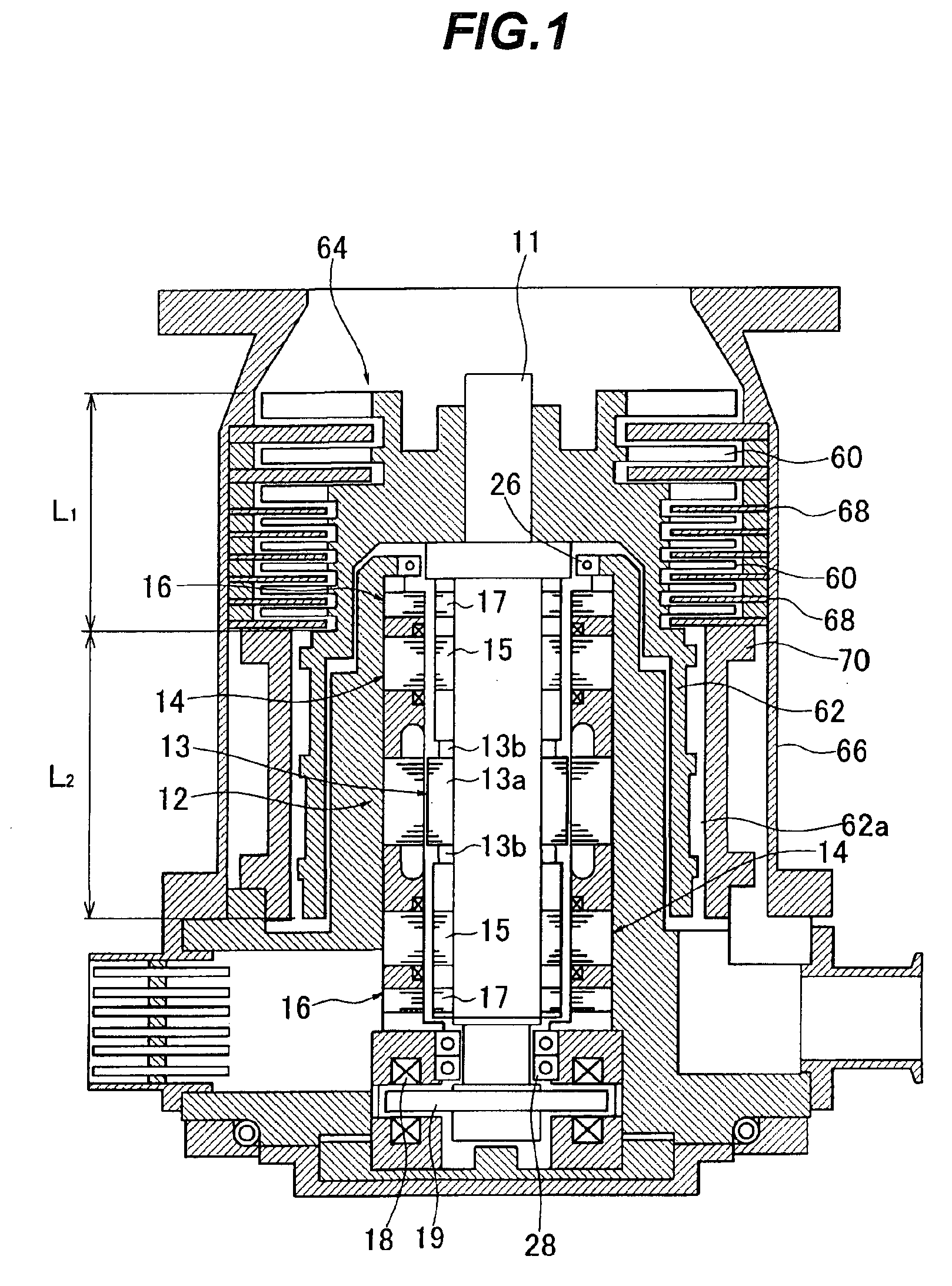
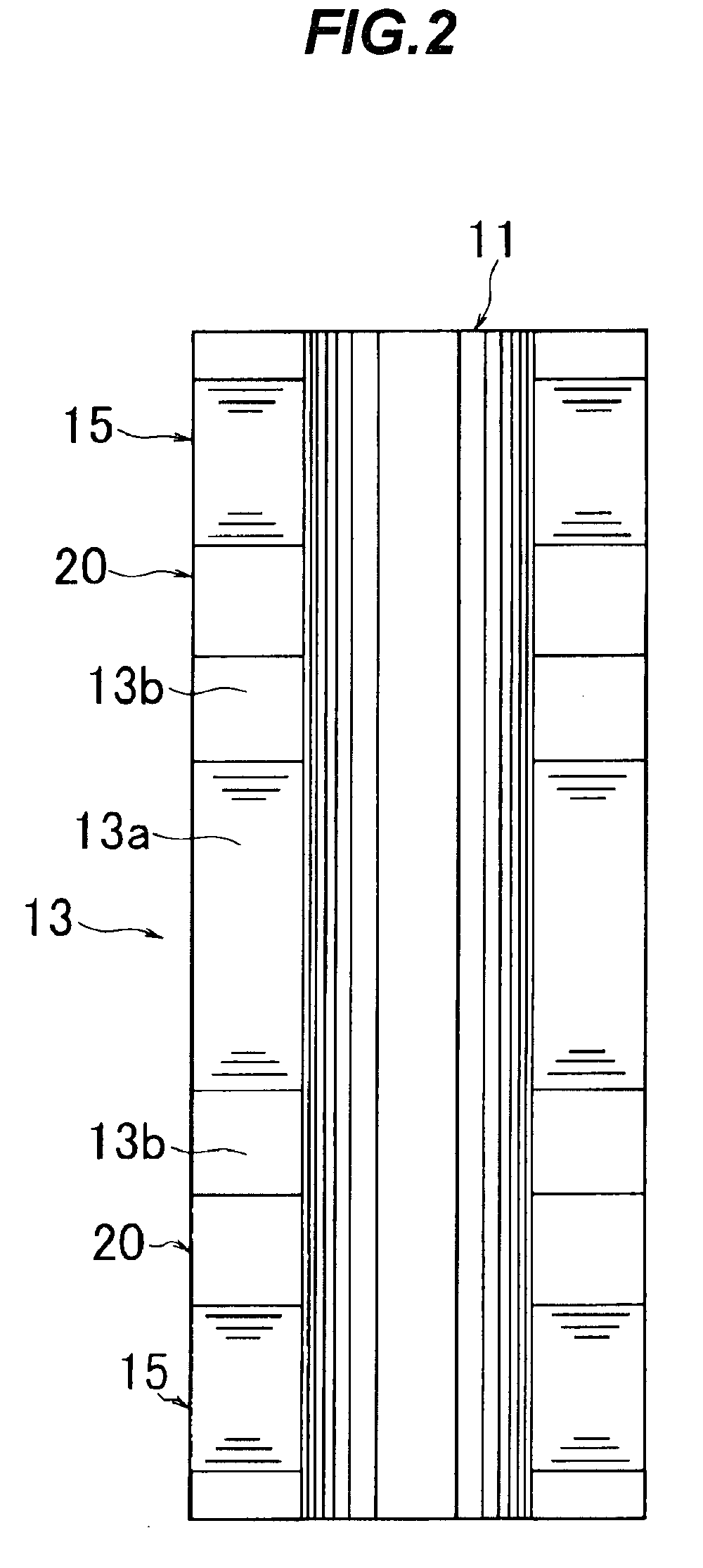
[0034]Preferred embodiments of the present invention will now be described with reference to the drawings. FIG. 4 is a cross-sectional diagram showing an embodiment of a rotor for use in a rotary apparatus according to the present invention, and FIG. 5 is an enlarged view of a portion of FIG. 4. The rotor 10 of this embodiment is a shaft assembly of a turbomolecular pump. The rotor 10 includes a rotor shaft 11. A motor rotor 13 of an induction motor, and targets 15, 15 of a radial magnetic bearing, disposed on both sides of the motor rotor 13, are fixed to the rotor shaft 11 and arranged in the axial direction with rotor spacers 20, 20 interposed between the targets 15, 15 and a motor rotor core 13a. The motor rotor 13 has the motor rotor core 13a in which conductors are disposed, and motor end rings 13b, which assemble and connect the conductors, are disposed on both sides of the motor rotor core 13a.

[0035]The rotor spacer 20 is a cylindrical shape and has, in its interior, a spac...


PUM


Abstract

A rotary apparatus, in which a rotor can rotate stably when it rotates at a high speed, can rotate at a relatively high speed by the torque of a highly reliable induction motor. The rotary apparatus comprises a rotor shaft and an induction motor. The induction motor includes a motor rotor core fixed to the rotor shaft, conductors disposed in the motor rotor core and a motor end ring for assembling and connecting the conductors, and can rotate the rotor shaft at a high speed by the torque. The rotor shaft is provided with a member that covers the motor end ring.

Description

BACKGROUND OF THE INVENTION[0001]1. Field of the Invention[0002]The present invention relates to a rotary apparatus in which a rotor shaft, to which a rotor of an induction motor is fixed, rotates at a relatively high speed by the torque of the induction motor.[0003]2. Description of the Related Art[0004]A turbomolecular pump is an example of a rotary apparatus in which a rotor shaft rotates at a relatively high speed. FIG. 1 is a cross-sectional diagram showing a conventional turbomolecular pump (see Japanese Patent Laid-Open Publication No. 2002-286036). The turbomolecular pump includes a rotor shaft 11 to which are integrally fixed a motor rotor 13 of an induction motor 12, targets 15, 15 of a radial magnetic bearing 14, sensingobjectportions 17, 17 of aradial displacement sensor 16, a target 19 of an axial magnetic bearing 18, and a sensing object portion (not shown) of an axial displacement sensor.[0005]A rotor (impeller) 64 having rotaryblades 60 and a threaded groove portion ...

Claims


Application Information

Patent Timeline
IPC IPC(8): H02K1/28
CPCF04D19/042H02K17/165H02K7/09F04D25/06
Inventor KAWASAKI, HIROYUKIMIYAMOTO, MATSUTARO
Owner EBARA CORP
Why Eureka
Try Eureka