Dc/dc Converter Device and Discharge Lamp Lighting Device

a technology of dc/dc converter and discharge lamp, which is applied in the direction of electric variable regulation, process and machine control, instruments, etc., can solve the problems of large ripple, devices cannot be adjusted in phase, and conventional devices cannot be developed to achieve efficiency improvement and noise reduction of dc/dc converter, so as to reduce ripple, reduce the capacitance of a filter capacitor, and reduce the effect of noise generation

Inactive Publication Date: 2009-04-30
MITSUBISHI ELECTRIC CORP
View PDF6 Cites 15 Cited by
  • Summary
  • Abstract
  • Description
  • Claims
  • Application Information

AI Technical Summary

Benefits of technology

[0018]The present invention is able to reduce ripple on both the input and output of the converter, reduce the capacitance of a capacitor for a filter, and reduce the noise generated by the ripple. Besides, the present invention is able to secure the lighting of a high-intensity discharge lamp.

Problems solved by technology

However, because both the transformers thereof are driven at the same frequency and with the same duty ratio, both the transformers cannot simultaneously resonate (the resonances of individual transformers are different from each other according to their element variations), and besides, the conventional device cannot be developed to a resonant DC / DC converter achieving efficiency improvement and noise reduction
However, since the device has a single configuration, its ripple is large, and its filter has to be reinforced to reduce the ripple.
Additionally, because a resonance is produced by the inductance of a transformer and a capacitor, if a plurality of devices are simply operated in parallel, their frequencies tend to be different from each other, and the devices cannot be adjusted in phase.
However, since a leakage reactor is used, its inductance becomes smaller than the inductance of the primary winding of the transformer, and the capacitor for resonance cannot but become large.
Additionally, the PFM control thereof becomes more complex in the circuit structure than a PFM control controlling the ON-time of a switching device by using a triangular wave, and therefore, is not suitable for a simple small ballast.
Furthermore, in the case of the conventional device disclosed in the Patent Document 4, since a lighting device is composed of a single DC / DC converter as in the case of the device disclosed in the above third patent document, the filter for reducing ripple cannot but be designed large.
In addition, in order to increase the efficiency of a DC / DC converter and reduce noise generation, the idea of combining the devices disclosed in the above first and second paten documents is seemingly easy; however, development to the resonant operation from the device disclosed in the above first patent document cannot be expected.

Method used


Image

  • Dc/dc Converter Device and Discharge Lamp Lighting Device
  • Dc/dc Converter Device and Discharge Lamp Lighting Device
  • Dc/dc Converter Device and Discharge Lamp Lighting Device

Examples


first embodiment

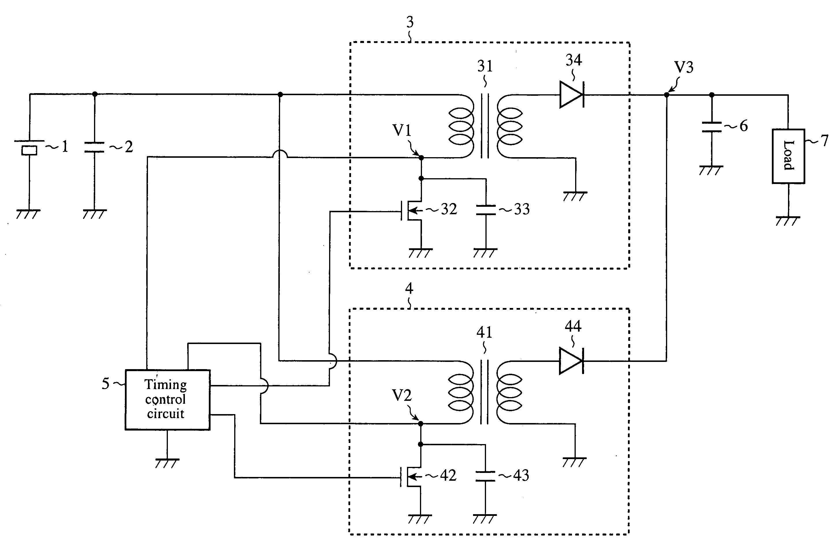
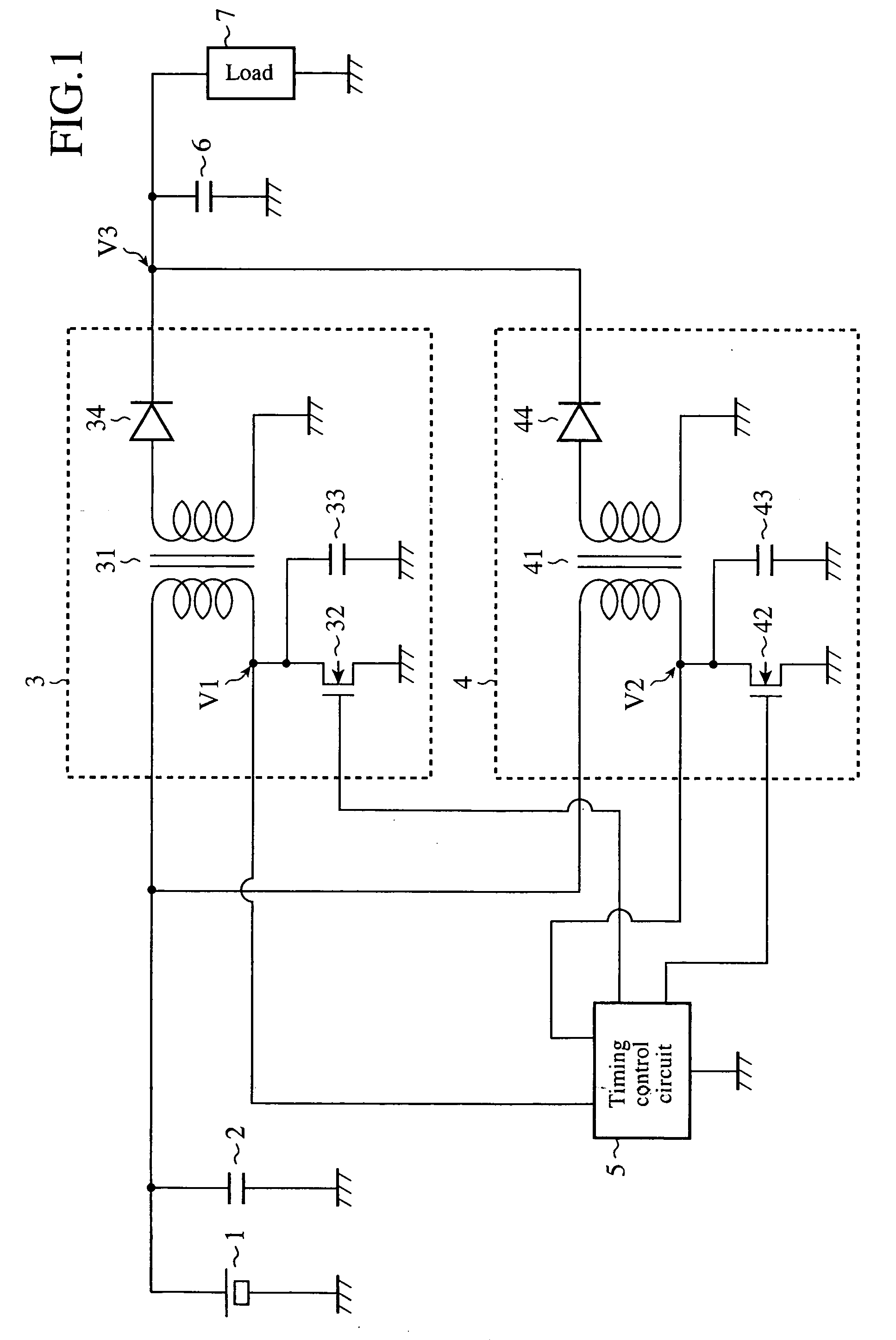
[0032]FIG. 1 is a block diagram showing a DC / DC converter device according to the first embodiment of the present invention.

[0033]In FIG. 1, a plurality of DC / DC converters 3, 4 are connected in parallel through a capacitor 2 connected in parallel with the two terminals of a battery 1, and a timing control circuit 5 is provided for the DC / DC converters 3, 4, and serves as a timing control means for controlling the ON / OFF timings of switching elements 32, 42 of the DC / DC converters 3, 4, respectively. Then, a load 7 is connected with the output side of the DC / DC converters 3, 4 through a capacitor 6.

[0034]Both one sides of the primary windings of a transformer 31 of the DC / DC converter 3 and a transformer 41 of the DC / DC converter 4 are connected with the positive side of the battery 1, and the other sides thereof are connected with the positive electrode (drain terminal) sides of the switching elements 32, 42, respectively, and are grounded through capacitors 33, 43, respectively.

[0...

second embodiment

[0047]FIG. 4 is a block diagram showing a DC / DC converter device according to the second embodiment of the present invention, in which a PLL circuit where the operating phase of the DC / DC converter is maintained in a predetermined phase is constructed.

[0048]Referring to FIG. 4, one side of the primary winding of a transformer 60 is connected with the positive side of a battery 11; and the other side thereof is connected with the positive electrode side of a switching element 61, and is connected with the inverting input terminal of a comparator 62. The non-inverting input terminal of the comparator 62 is grounded; the output terminal thereof is connected with the base of a transistor 64 through a capacitor 63; the emitter of the transistor 64 is grounded; the collector thereof is connected with the node between a resistor 65 and a capacitor 66 connected in series between the power source of 5 V and the ground; and the node is connected with the inverting input terminal of the compar...

third embodiment

[0063]FIG. 11 is a block diagram showing a DC / DC converter device according to the third embodiment of the present invention. The embodiment is virtually the case where the DC / DC converter device according to the present invention is specially applied to an electric-discharge lamp lighting device.

[0064]FIG. 7 is used for explaining the operation of the circuit shown in FIG. 11, and shows one side of the circuit shown in FIG. 11. Referring to FIG. 7, one side end of the primary winding of a transformer 101 is connected to a battery 21, and the other end of the primary winding of the transformer 101 is connected with the positive electrode (drain terminal) side of a switching element 102, and is grounded through a capacitor 103.

[0065]Further, one side of the secondary winding of the transformer 101 is connected with a capacitor 22 through a diode 104, and is connected with an H type bridge circuit 24 consisting of four switching elements connected in parallel via a node 23 to which ou...


PUM


Abstract

A DC/DC converter device according to the present invention includes a plurality of resonant DC/DC converters 3, connected in parallel, and a timing control circuit 5 driving the plurality of resonant DC/DC converters at substantially the same frequency with a phase shift.

Description

TECHNICAL FIELD[0001]The present invention relates to a DC / DC converter device well adapted for installation on vehicles or the like, and a discharge lamp lighting device with the DC / DC converter device.BACKGROUND ART[0002]This type of conventional converters include a converter where a plurality of small-capacity DC / DC converters are connected in parallel, and are operated in parallel with shifting each operating phase of these converters in order to compose a single DC / DC converter (see Patent Document 1, for example).[0003]Further, known converters include a converter where a DC-DC converter is operated synchronously with the resonance of a coil capacitor circuit containing the inductance of a transformer of the DC / DC converter by detecting the current applied to the transformer or the voltage of the node between a switching device and the transformer to detect the time point when the current becomes 0 A or the time point when the voltage becomes 0 V (see Patent Document 2, for e...

Claims


Application Information

Patent Timeline
Patent Type & Authority Applications(United States)
IPC IPC(8): H02M3/22H05B41/26
CPCH02M3/285H05B41/288Y02B70/1491H02M2001/0058H05B41/2882H02M1/0058Y02B70/10
Inventor KOHNO, YASUHIKOOHSAWA, TAKASHI
Owner MITSUBISHI ELECTRIC CORP
Why Eureka
Try Eureka