Localized charging, load identification and bi-directional communication methods for a planar inductive battery charging system

a charging system and inductive battery technology, applied in the direction of charging devices, exchanging data, inductances, etc., can solve the problems of inconvenient use, electronic waste, and difficulty in designing a slim energy-receiving module that can be unobtrusively housed inside the charging equipment, so as to optimize the performance of the battery charging system

Inactive Publication Date: 2009-04-30
CITY UNIVERSITY OF HONG KONG
View PDF7 Cites 69 Cited by
  • Summary
  • Abstract
  • Description
  • Claims
  • Application Information

AI Technical Summary

Benefits of technology

[0017]In preferred embodiments of the invention, the array of primary windings comprise a plurality of rows and a plurality of columns, wherein the matrix switching array comprises one switch per row and one switch per column, and wherein a winding to be excited is selected by closing the switches in the row and column corresponding to the location of the winding. The switches may be controlled by a microprocessor control unit and the matrix switching array preferably includes filter means to prevent the generation of EMI interference.

Problems solved by technology

This number is both inconvenient to users and eventually leads to electronic waste problems.
However, these battery chargers do not use a planar structure and each charger is able to charge only one electronic load at a time.
However, such a horizontal flux approach requires a vertical surface to pick up the ac flux for voltage induction (FIG. 1(b)) and this limitation makes it difficult to design a slim energy-receiving module that can be unobtrusively housed inside the equipment to be charged.
Although the concept of a “localized charging principle” has been disclosed previously in GB2389720A, U.S. Pat. No. 7,1642,55 and WO2007 / 019806, so far there is no systematic approach in designing an inductive battery charging pad that can meet the energy-efficiency, safety, electromagnetic compatibility requirements simultaneously.
1-4,” a MEMS method has been proposed for inductive charging system, but such approach is restricted to relatively low-power and is very costly.

Method used


Image

  • Localized charging, load identification and bi-directional communication methods for a planar inductive battery charging system
  • Localized charging, load identification and bi-directional communication methods for a planar inductive battery charging system
  • Localized charging, load identification and bi-directional communication methods for a planar inductive battery charging system

Examples


Embodiment Construction

[0034]Preferred embodiments of the present invention provide a systematic methodology that covers a range of technical aspects of an inductive battery charging system. Such a system includes a charging platform or pad that generates vertical flux from the planar surface of the charging pad and at least in preferred embodiments the present invention addresses several basic principles for achieving localized charging in a charging pad system. Although these principles and corresponding techniques can be implemented individually, their collective use is synergistic and enables the development of an inductive charging pad system that can meet various international regulatory requirements.

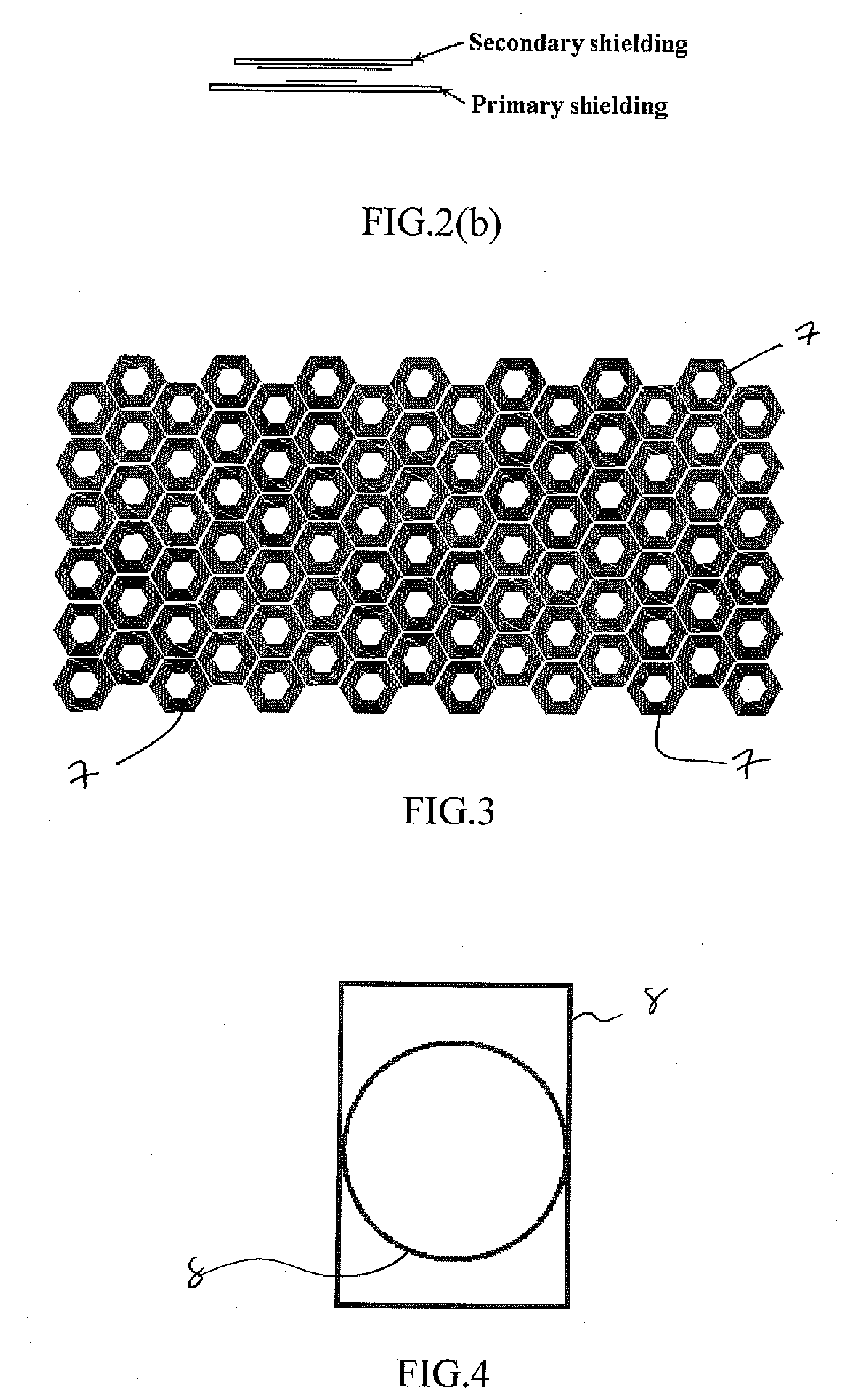
[0035]FIG. 3 shows a typical single-layer winding array structure with many individual primary energy-transmitting coils 7 (named transmitter windings hereafter) in an inductive battery charging pad. It is also proposed that a multilayer winding array can also be used. For example, a stacked winding whe...


PUM


Abstract

Methods and principles are described for systematizing localized charging, load identification and bi-directional communication in a planar battery charging system. Also described is control circuitry for selectively energizing a primary winding when a load is placed on the platform. The optimization of the size of the receiver winding compared to the transmitter winding is discussed, while the associated communication methods include techniques for load identification, compatibility checks, hand-shaking and communication of charging status.

Description

FIELD OF THE INVENTION[0001]This invention relates to localized charging, load identification and bi-directional communication methods for use in a planar battery charging system.BACKGROUND OF THE INVENTION[0002]The increasing popularity of portable consumer electronic products such as mobile phones, MP3 players and PDAs has prompted new concerns on the huge variety and number of battery chargers that are required. This number is both inconvenient to users and eventually leads to electronic waste problems. Inductive or wireless charging apparatus that can charge more than one electronic product have been proposed. Two different approaches have been proposed for the ac magnetic flux generation, namely “horizontal flux” and “vertical flux” method.[0003]Inductive electronic chargers have been developed for use with some types of portable electronic equipment such as electric toothbrushes. Inductive chargers have also been proposed in U.S. Pat. No. 6,356,049, U.S. Pat. No. 6,301,128, an...

Claims


Application Information

Patent Timeline
Patent Type & Authority Applications(United States)
IPC IPC(8): H02J7/00
CPCH01F38/14H02J7/025H01F2017/0073H02J50/10H02J7/00034H02J50/90H02J50/402H02J50/80H02J50/70
Inventor LIU, XUNHO, WING CHOIHUI, RON SHU YUENCHAN, WING CHEONG
Owner CITY UNIVERSITY OF HONG KONG
Why Eureka
Try Eureka