Bandwidth control in a mostly-digital pll/fll

a technology of mostly digital and frequency-locked loops, applied in the direction of automatic control, electrical equipment, etc., can solve the problems of circuit arrangements not enjoying the benefits of ddfs, circuit arrangement disturbance, and output signal transitions that are not purious, so as to reduce disturbances, improve frequency switching time, and improve the effect of frequency switching speed

Inactive Publication Date: 2009-04-30
PANASONIC CORP
View PDF4 Cites 44 Cited by
  • Summary
  • Abstract
  • Description
  • Claims
  • Application Information

AI Technical Summary

Benefits of technology

[0014]According to one aspect of the invention, one or more of the programmable filter parameters of the digital loop filter are changed by increments during operation, in order to minimize disturbances (e.g., settling transients) as the loop bandwidth of the PLL is varied from a narrow loop bandwidth to a wide loop bandwidth, or vice versa. By changing the loop filter parameters gradually, i.e., in increments, the loop bandwidth can be varied with substantially no perturbation. The end result is a much faster frequency switching time, improved settling dynamics, and predictable and stable loop operating performance.
[0015]According to another aspect of the invention, one or more of the programmable filter parameters are changed in order to oppose a change in tuning sensitivity of the controlled oscillator (e.g., in order to maintain a constant loop bandwidth). A benefit of this aspect of the invention is that by holding the loop bandwidth constant, switching time is maintained substantially constant under all conditions. This is a very desirable design condition, since it reduces design and production margins in a frequency agile system. It also relaxes the tuning sensitivity linearity requirements of the controlled oscillator.

Problems solved by technology

One of the challenges of DDFS has been to generate a clean, precisely-modulated waveform.
Because of limited time resolution and edge misalignment, spurious output signal transitions (i.e., “spurs”) occur.
Precision modulation is also a problem in conventional analog frequency synthesizers using a phase-locked loop (PLL).
The problem occurs that the PLL treats signal modulation as drift and attempts to cancel the modulation.
Such circuit arrangements do not enjoy the benefits of DDFS.

Method used


Image

  • Bandwidth control in a mostly-digital pll/fll
  • Bandwidth control in a mostly-digital pll/fll
  • Bandwidth control in a mostly-digital pll/fll

Examples


Embodiment Construction

[0028]Those of ordinary skill in the art will realize that the following detailed description of the present invention is illustrative only and is not intended to be in any way limiting. Other embodiments of the present invention will readily suggest themselves to such skilled persons having the benefit of this disclosure. Reference will now be made in detail to implementations of the present invention as illustrated in the accompanying drawings. The same reference indicators will be used throughout the drawings and the following detailed description to refer to the same or like parts.

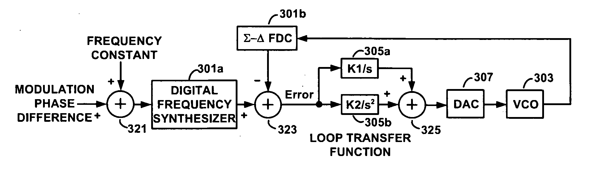
[0029]Referring now to FIG. 3, there is shown a block diagram of a PLL / FLL in accordance with one aspect of the present invention. A frequency constant is applied to an adder 321 together with a modulation phase difference signal. A resulting sum is applied to a digital frequency synthesizer (DFS) 301a. The DFS 301a outputs a stream of bits representing a desired frequency of a VCO 303, an output signa...


PUM


Abstract

Methods and apparatus for controlling a controlled oscillator using a phase-locked loop (PLL) or frequency-locked loop (FLL) having a digital loop filter with programmable filter parameters. An exemplary PLL (or FLL) includes a digital loop filter having one or more of the programmable filter parameters, which are changed by increments during operation in order to minimize disturbances (e.g., settling transients) as the loop bandwidth of the PLL is varied from a narrow loop bandwidth to a wide loop bandwidth, or vice versa. By changing the loop filter parameters in increments the loop bandwidth can be varied with substantially no perturbation. The end result is a much faster frequency switching time, improved settling dynamics, and predictable and stable loop operating performance. According to another aspect of the invention, one or more of the programmable filter parameters are changed in order to oppose a change in tuning sensitivity of the controlled oscillator (e.g., in order to maintain a constant loop bandwidth). By holding the loop bandwidth constant, switching time is maintained substantially constant under all conditions. This allows design and production margins to be reduced in a frequency agile system, and also relaxes the tuning sensitivity linearity requirements of the controlled oscillator.

Description

CROSS-REFERENCE TO RELATED APPLICATIONS[0001]This patent application claims the benefit of U.S. Provisional Patent Application No. 60 / 983,136, filed on Oct. 26, 2007, the disclosure of which is hereby incorporated by reference.FIELD OF THE INVENTION[0002]The present invention relates to phase-locked loops (PLLs) and frequency-locked loops (FLLs), particularly loops of mostly-digital construction.BACKGROUND OF THE INVENTION[0003]Direct digital frequency synthesis (DDFS) consists of generating a digital representation of a desired signal, using logic circuitry and / or a digital computer, and then converting the digital representation to an analog waveform using a digital-to-analog converter (DAC). Such systems can be compact, low power, and can provide very fine frequency resolution with virtually instantaneous switching of frequencies.[0004]One of the challenges of DDFS has been to generate a clean, precisely-modulated waveform. Because of limited time resolution and edge misalignment...

Claims


Application Information

Patent Timeline
Patent Type & Authority Applications(United States)
IPC IPC(8): H03L7/06
CPCH03L7/085H03L7/1075H03L7/107
Inventor SANDER, WENDELLSANDER, BRIAN
Owner PANASONIC CORP
Why Eureka
Try Eureka