Bootstrap circuit and step-down converter using same

a step-down converter and step-down converter technology, applied in the field of step-down converters, can solve the problems of output ripple, and other side effects, and achieve the effects of avoiding the effect of output ripple, power supply efficiency worsening, and avoiding the effect of step-down converters during capacitor cb charging

Inactive Publication Date: 2009-04-30
FUJI ELECTRIC CO LTD
View PDF8 Cites 37 Cited by
  • Summary
  • Abstract
  • Description
  • Claims
  • Application Information

AI Technical Summary

Benefits of technology

[0012]The invention provides a bootstrap circuit which enables adequate charging of the capacitor used in the bootstrap circuit even during light load or no load, and which does not impede the performance of the step-down converter proper, as well as a step-down converter using such a circuit.
[0014]In a bootstrap circuit of this invention, the CB-terminal of the capacitor CB used in the bootstrap circuit is connected, via the capacitor charge / discharge path formation means, to the step-down converter circuit, and by this means the path for charging the capacitor CB used in the bootstrap circuit is made independent. As a result, effects on the step-down converter during charging of the capacitor CB, that is, the occurrence of power supply efficiency worsening, increases in output ripple, and other side effects, can be avoided. Moreover, the capacitor CB used in the bootstrap circuit can always be charged with stability, regardless of the load state, such as for example when the load is light or there is no load.
[0015]Further, a step-down converter including a bootstrap circuit of this invention includes a bootstrap circuit having capacitor charge / discharge path formation mechanism; the CB-terminal of the capacitor CB used in the bootstrap circuit is connected, via the capacitor charge / discharge path formation mechanism, to the step-down converter circuit, and by this mechanism the current path to charge the capacitor CB used in the bootstrap circuit is made independent. As a result, effects on the step-down converter during charging of the capacitor CB, that is, the occurrence of power supply efficiency worsening, increases in output ripple, and other side effects, can be avoided, so that stable operation and improved power supply efficiency of the step-down converter circuit can be expected. Moreover, the capacitor CB used in the bootstrap circuit can always be charged with stability, regardless of the load state, such as for example when the load is light or there is no load.

Problems solved by technology

In this case, by changing the source-side potential of the switching device Q1, that is, by changing the inductor current, the current path of the step-down converter itself is affected, so that compared with the step-down converter proper without a bootstrap circuit, power supply efficiency worsening, increases in output ripple, and other side-effects occur, and so there is the problem that the performance of the step-down converter proper is impeded.
During light load, the charging time is lengthened to a certain extent, so that instantaneous driving capacity can be secured, but on the other hand, because the time during which charging is not possible (that is, the discharge interval) is also lengthened, the charged voltage falls immediately, and as the frequency is lowered, there is the problem that the time over which driving capacity is insufficient is also longer.

Method used


Image

  • Bootstrap circuit and step-down converter using same
  • Bootstrap circuit and step-down converter using same
  • Bootstrap circuit and step-down converter using same

Examples


first embodiment

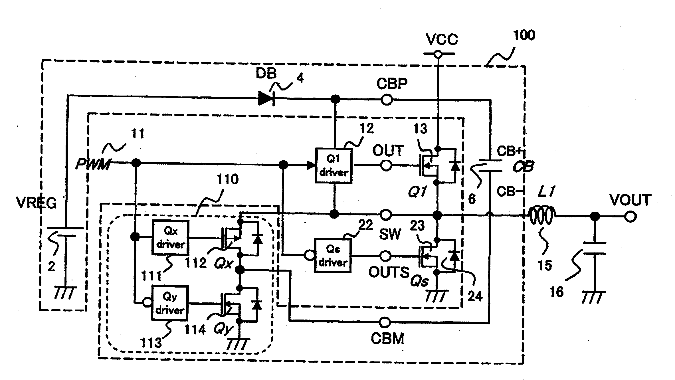
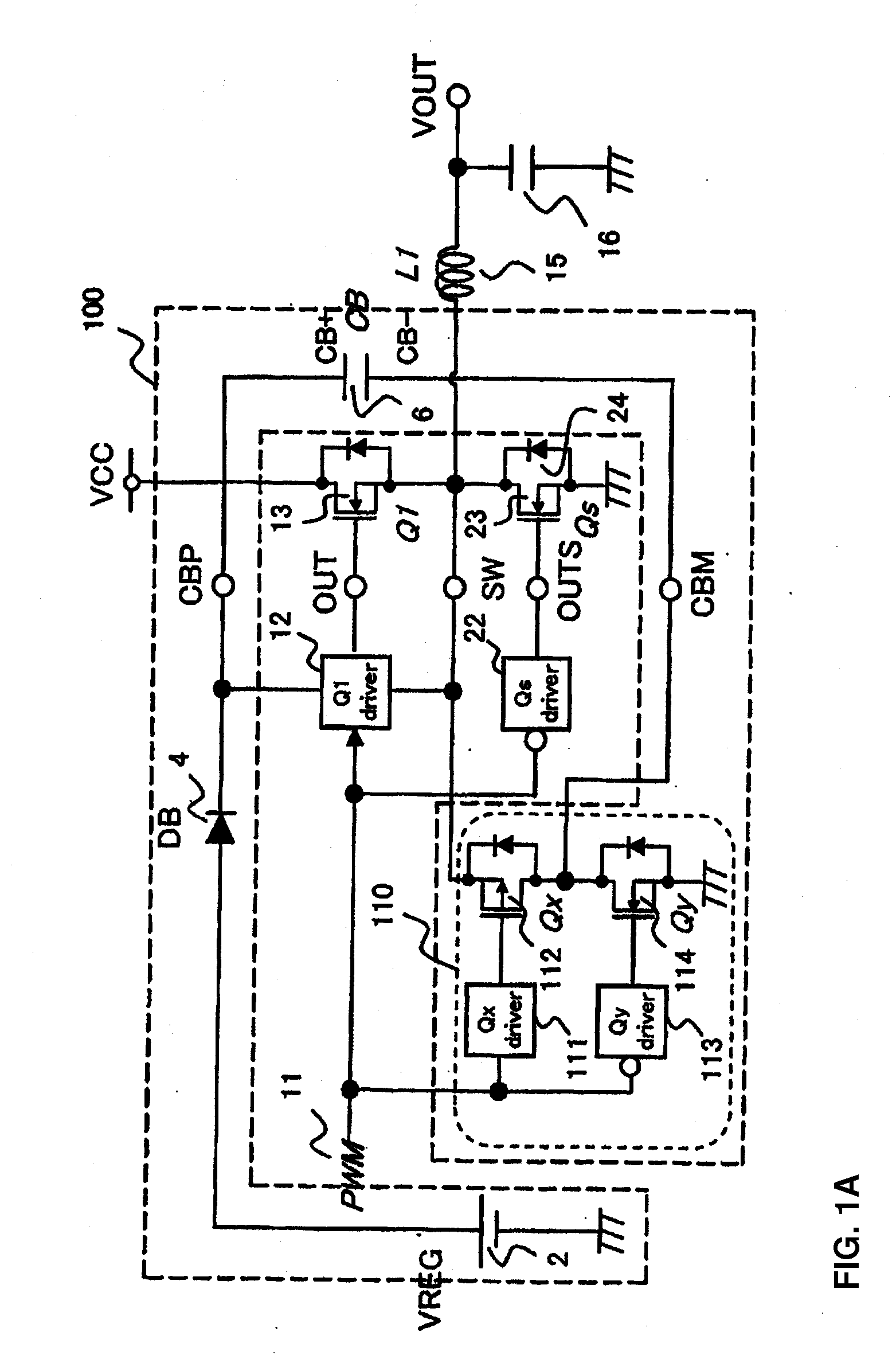
[0039]In this first embodiment of a step-down converter comprising a bootstrap circuit of an aspect of this invention, a bootstrap circuit is comprised having capacitor charge / discharge path formation mechanism or means, and by connecting the CB-terminal of the capacitor CB used in the bootstrap circuit to the step-down converter circuit via the capacitor charge / discharge path formation mechanism, the current path to charge the capacitor CB used in the bootstrap circuit can be made independent. As a result, effects on the step-down converter circuit, that is, the occurrence of power supply efficiency worsening, increases in output ripple, and other side effects, can be avoided, so that stable operation and improved power supply efficiency of the step-down converter circuit can be expected. Moreover, the capacitor CB used in the bootstrap circuit can always be charged with stability, regardless of the load state, such as for example when the load is light or there is no load.

[0040]FI...

second embodiment

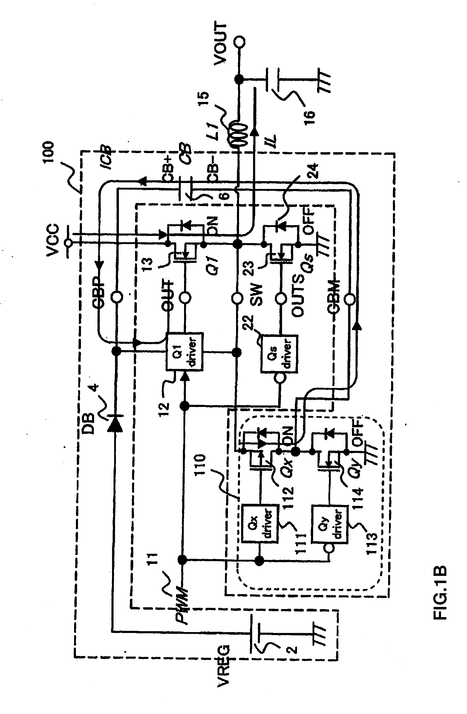
[0043]In this second embodiment of a step-down converter comprising a bootstrap circuit of an aspect of this invention, a bootstrap circuit is comprised having capacitor charge / discharge path formation mechanism or means, and by connecting the CB-terminal of the capacitor CB used in the bootstrap circuit to the step-down converter circuit via the capacitor charge / discharge path formation mechanism, the current path to charge the capacitor CB used in the bootstrap circuit can be made independent. As a result, effects on the step-down converter circuit, that is, the occurrence of power supply efficiency worsening, increases in output ripple, and other side effects, can be avoided, so that stable operation and improved power supply efficiency of the step-down converter circuit can be expected. Moreover, the capacitor CB used in the bootstrap circuit can always be charged with stability, regardless of the load state, such as for example when the load is light or there is no load.


PUM


Abstract

The invention provides a bootstrap circuit which enables adequate charging of a capacitor used in the bootstrap circuit even during light load or no load conditions, and which does not impede the performance of a step-down converter proper, as well as a step-down converter using the bootstrap circuit. A capacitor charge / discharge path formation mechanism is provided in the bootstrap circuit that enables a terminal of a capacitor used in the bootstrap circuit to be separated and made independent from a step-down converter circuit.

Description

BACKGROUND OF THE INVENTION[0001]The invention relates to a bootstrap circuit which, in order to perform switching control by applying a voltage from a driver to a gate of a switching device which uses an N-channel MOSFET having a drain to which an input voltage is supplied, has a capacitor which steps up a power supply voltage of the driver to the input voltage or higher, as well as a step-down converter using this circuit, and in particular this invention enables adequate charging of a capacitor used in a bootstrap circuit even during light load or no load.[0002]In a step-down converter (step-down type DC-DC converter) which uses an N-channel MOSFET as a switching device, a circuit (generally called a bootstrap circuit), having a capacitor which steps up the power supply voltage of the driver to the input voltage for input to the switching device or higher, in order to apply the high-side driver voltage to the gate of the switching device and perform switching control, is necessar...

Claims


Application Information

Patent Timeline
Patent Type & Authority Applications(United States)
IPC IPC(8): H02M3/158
CPCH02M1/08Y02B70/1466H02M2001/0006H02M3/1588Y02B70/10H02M1/0006
Inventor YAMADAYA, MASAYUKI
Owner FUJI ELECTRIC CO LTD
Why Eureka
Try Eureka