High power commutating multiple output amplifier system

a multi-output amplifier, high-power technology, applied in amplifiers, amplifiers with coupling networks, amplifiers with semiconductor devices/discharge tubes, etc., can solve the problems of ferrite switches, pin diodes add significant loss and weight, mechanical switches are limited by reliability and speed,

Active Publication Date: 2009-04-30
RAYTHEON CO
View PDF6 Cites 24 Cited by
  • Summary
  • Abstract
  • Description
  • Claims
  • Application Information

AI Technical Summary

Benefits of technology

[0003]An exemplary embodiment of an amplifier system includes a power divider for dividing an input RF signal into M RF signals of equal power and phase. An exemplary embodiment of the system has M low power selectable phase shifters each for phase shifting one of the M RF signals. M high power amplifiers are coupled to respective ones of the phase shifters. An exemplary embodiment includes an M×N power distribution network having M input ports and N output ports, such as a Butler matrix. The M high power amplifiers are connected to a respective one of the M input ports of the distribution network. The phase of the M phase shifters may be adjusted to obtain a maximum output at the desired output with all the other outputs nulled.

Problems solved by technology

Mechanical switches are limited by reliability and speed.
PIN diode switches add significant loss and weight.
Ferrite switches add loss, weight and driver complexity.

Method used


Image

  • High power commutating multiple output amplifier system
  • High power commutating multiple output amplifier system
  • High power commutating multiple output amplifier system

Examples


Embodiment Construction

[0009]In the following detailed description and in the several figures of the drawing, like elements are identified with like reference numerals. The figures are not to scale, and relative feature sizes may be exaggerated for illustrative purposes.

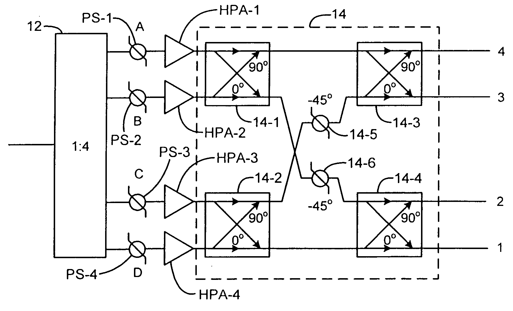
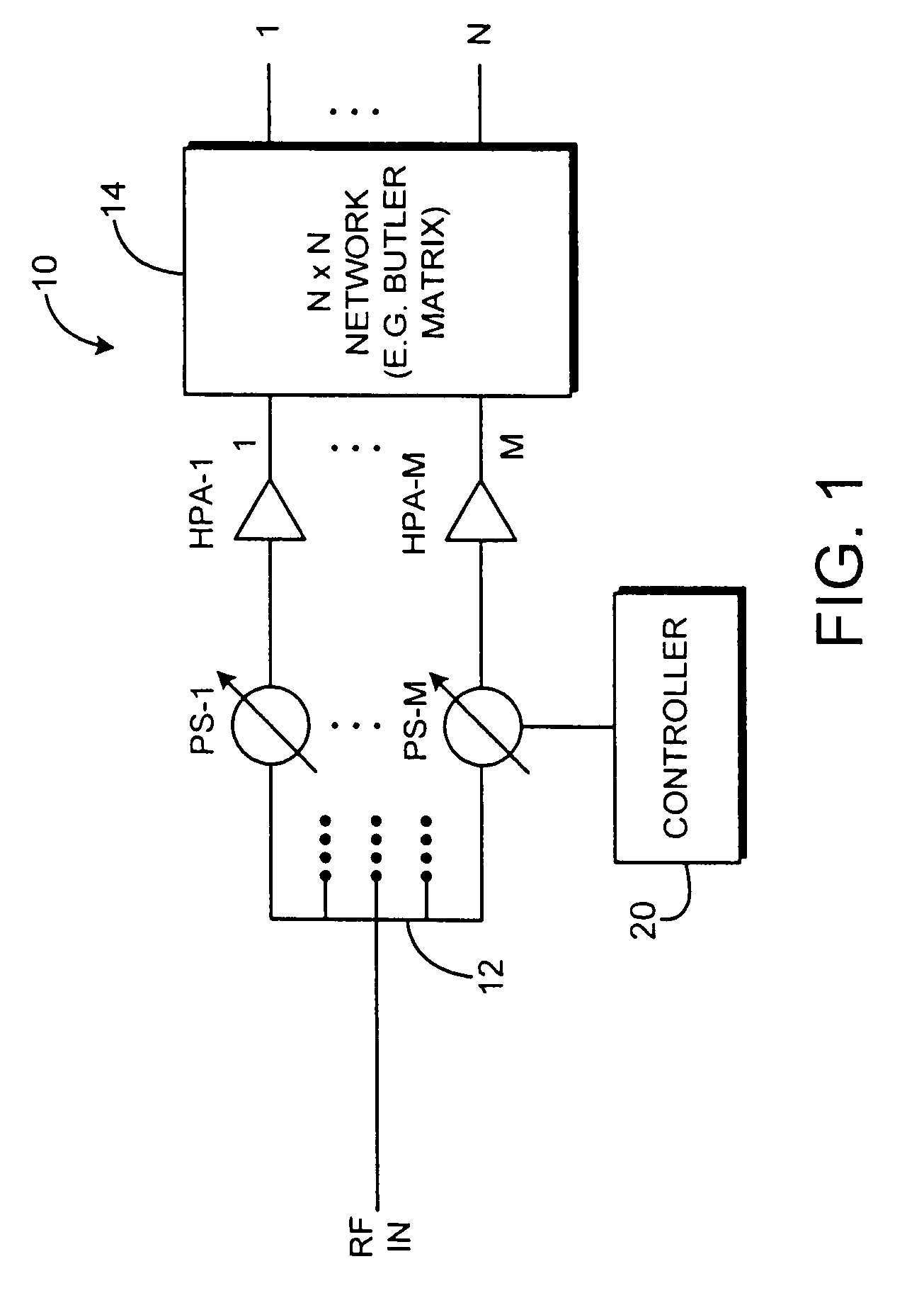
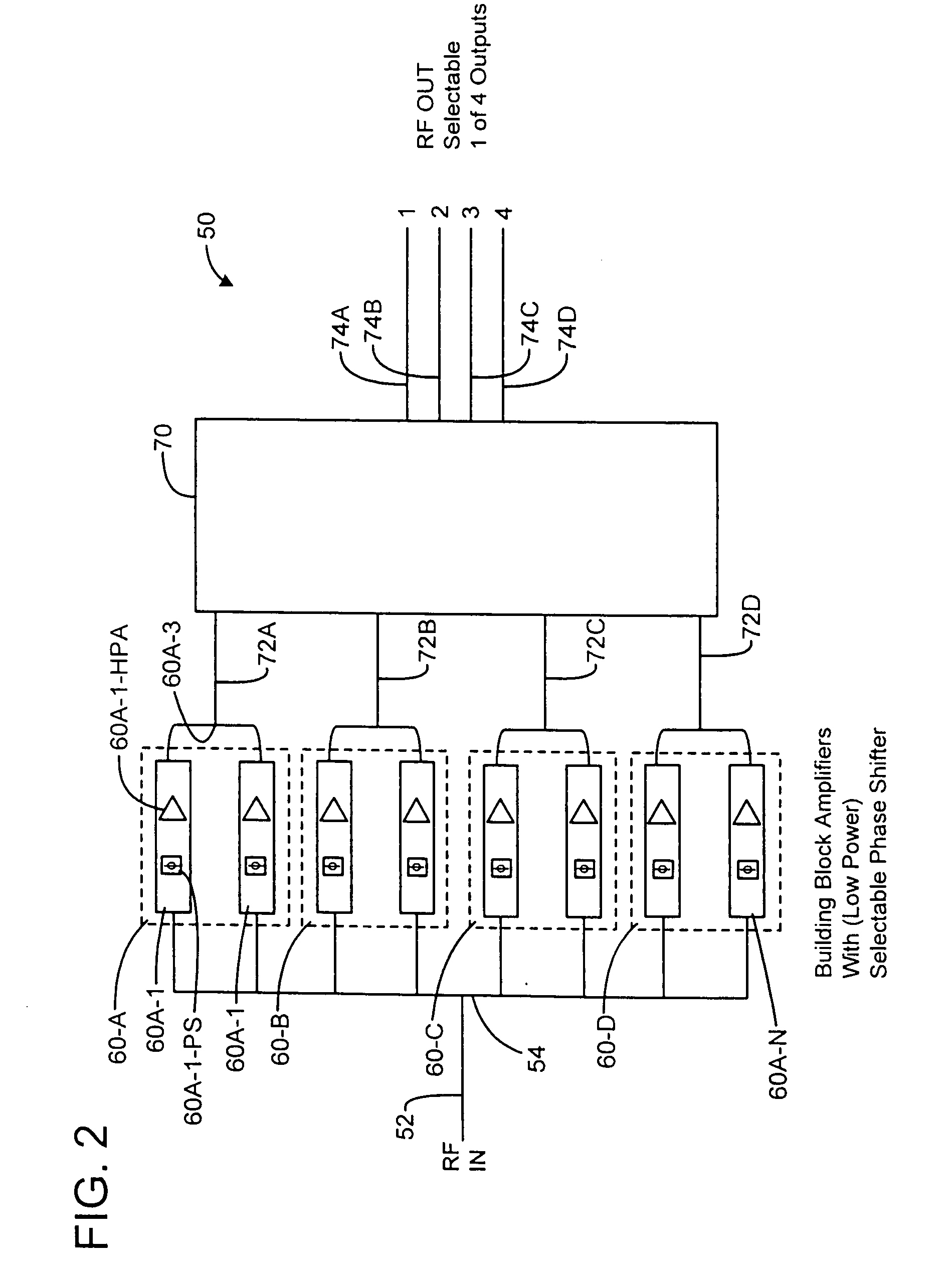
[0010]A high power amplifier system with integrated switching to provide selectable outputs is described. In an exemplary embodiment, a system includes low power phase shifters, prior to high power amplification to adjust the phase of a high power amplifier building block (e.g. a solid state amplifier, or a traveling wave tube amplifier, or “TWTA”). The outputs of these building block amplifiers are fed into a distribution network such as a Butler matrix. The phase of each of the individual building block amplifiers may be adjusted to obtain maximum output at the desired output and null all the other outputs, i.e., have little or no output. An exemplary embodiment of an amplifier system may provide the ability to switch high power microwav...


PUM


Abstract

An amplifier system includes a power divider for dividing an input RF signal into M RF signals of equal power and phase. The system has M low power selectable phase shifters each for phase shifting one of the M RF signals. M high power amplifiers are coupled to respective ones of the phase shifters. The system includes an M×N power distribution network having M input ports and N output ports, such as a Butler matrix. The M high power amplifiers are connected to a respective one of the M input ports of the distribution network. The phase of the M phase shifters may be adjusted to obtain a maximum output at the desired output with all the other outputs nulled.

Description

BACKGROUND[0001]Several methods have been used to provide selectable outputs on a high power transmitter. All use a switch circuit or device to select the output. Mechanical switches are limited by reliability and speed. PIN diode switches add significant loss and weight. Ferrite switches add loss, weight and driver complexity.[0002]Signal distribution networks such as Butler matrices are well known in the art, and examples are described, e.g. in U.S. Pat. No. 3,255,450, which describes a binary network matrix, and U.S. Pat. No. 4,638,317, which describes a matrix with a non-binary set of outputs.SUMMARY OF THE DISCLOSURE[0003]An exemplary embodiment of an amplifier system includes a power divider for dividing an input RF signal into M RF signals of equal power and phase. An exemplary embodiment of the system has M low power selectable phase shifters each for phase shifting one of the M RF signals. M high power amplifiers are coupled to respective ones of the phase shifters. An exem...

Claims


Application Information

Patent Timeline
Patent Type & Authority Applications(United States)
IPC IPC(8): H03F3/68H03F3/60
CPCH03F3/602H03F2200/451H03F3/68
Inventor GANDHI, CHETANLIVINGSTON, STAN W.KRUEGER, REINHARDT W.
Owner RAYTHEON CO
Why Eureka
Try Eureka