Fuel Cell System

Active Publication Date: 2009-04-30
TOYOTA JIDOSHA KK
View PDF9 Cites 13 Cited by
  • Summary
  • Abstract
  • Description
  • Claims
  • Application Information

AI Technical Summary

Benefits of technology

[0010]As described above, according to the present invention, the highly

Problems solved by technology

Therefore, when the fluctuation of the cell voltage is actually detected and then an amount of an oxidizing gas is determined, a certain abnormality (dry-up, floo

Method used


Image

  • Fuel Cell System
  • Fuel Cell System
  • Fuel Cell System

Examples


Embodiment Construction

[0016]An embodiment of the present invention will hereinafter be described with reference to the drawings.

A. Present Embodiment

A-1. Whole Constitution

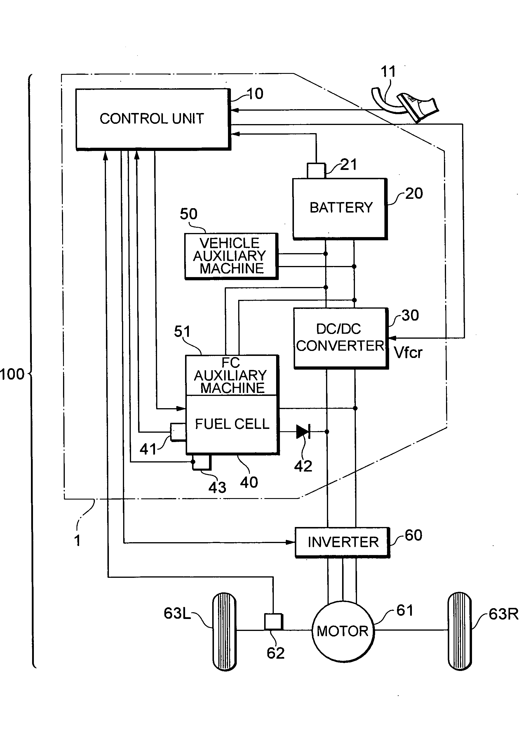
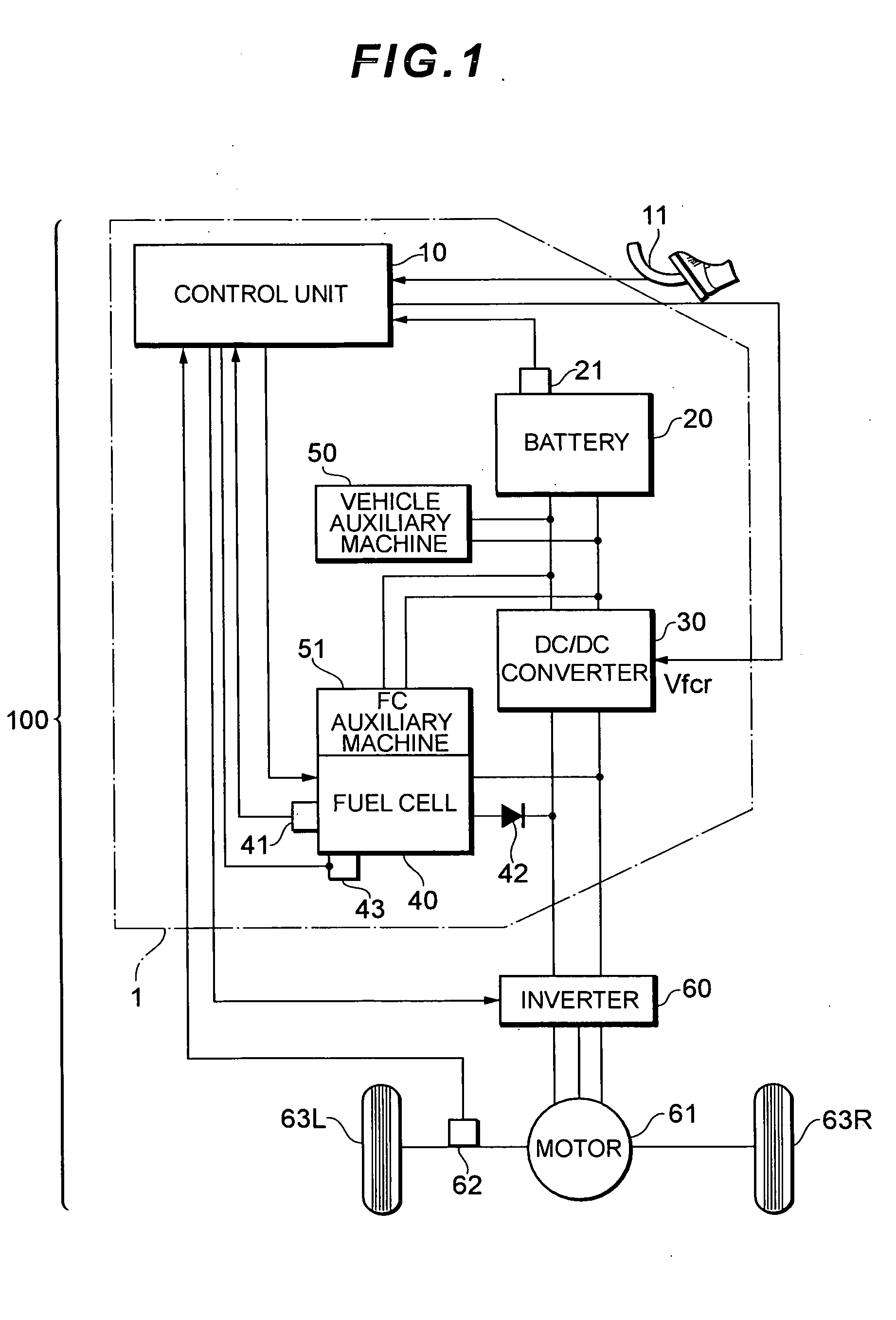
[0017]FIG. 1 is a schematic constitution diagram of a vehicle on which a fuel cell system 100 according to the present embodiment is mounted. It is to be noted that in the following description, a fuel cell hybrid vehicle (FCHV) is assumed as one example of a vehicle, but the present embodiment is also applicable to an electric car and a hybrid car. The embodiment is applicable to not only the vehicle but also various mobile bodies (e.g., a boat, an airplane, etc.).

[0018]This vehicle runs using a driving power source which is a synchronous motor 61 connected to wheels 63L, 63R. A power source of the synchronous motor 61 is a power supply system 1. A direct current output from the power supply system 1 is converted into a three-phase alternating current by an inverter 60, and supplied to the synchronous motor 61. The synchronous motor 6...


PUM


Abstract

A fuel cell system according to the present invention is characterized by comprising a measurement unit which measures an impedance of a fuel cell in a predetermined frequency region, and a regulation unit which regulates an amount of a gas to be supplied to the fuel cell based on a measured value of the impedance in the predetermined frequency region. According to such a constitution, the impedance of the fuel cell in the predetermined frequency region (e.g., a low frequency region) is measured, and the amount of the gas (e.g., an amount of an oxidizing gas) to be supplied to the fuel cell is regulated based on this measured value of the impedance. Here, since the impedance of the fuel cell in the predetermined frequency region largely differs with a fuel supply state (see FIG. 2), the amount of the gas to be supplied to the fuel cell can be regulated based on the measured value of the impedance to realize a highly efficient and stable operation.

Description

TECHNICAL FIELD[0001]The present invention relates to a fuel cell system. More particularly, it relates to a fuel cell system which measures an impedance by use of an alternating-current impedance process.BACKGROUND ART[0002]In a fuel cell system, a fuel cell of a solid polymer type including a solid polymer film having proton conductivity in an electrolytic layer is mounted. When the solid polymer film of this fuel cell is in a wetted state, the film exhibits high proton conductivity, so that it is important to keep the solid polymer film in the wetted state in order to efficiently generate a power. In order to keep such a solid polymer film in the wetted state, a water exchange type humidifier (hereinafter referred to simply as the “humidifier”) is utilized which performs water exchange between an oxidizing off gas to be discharged from a cathode side of the fuel cell and an oxidizing gas to be supplied to the cathode side of the fuel cell via a water vapor transmission film.[0003...

Claims


Application Information

Patent Timeline
IPC IPC(8): H01M8/04
CPCH01M8/04007H01M8/04089H01M8/04649Y02T90/32H01M2008/1095H01M2250/20Y02E60/50H01M8/04753Y02T90/40H01M8/04
Inventor MANABE, KOTAORIHASHI, NOBUYUKIHAMADA, SHIGETAKASHIGE, MASAHIRO
Owner TOYOTA JIDOSHA KK
Why Eureka
Try Eureka