Method and apparatus for controlling combustion in a burner

Active Publication Date: 2009-04-30
WEBSTER COMBUSTION TECH LLC
View PDF19 Cites 45 Cited by
  • Summary
  • Abstract
  • Description
  • Claims
  • Application Information

AI Technical Summary

Benefits of technology

[0027]In another embodiment, a method of combustion control in a burner is disclosed comprising the step of processing both a first signal corresponding to an absolute barometric pressure measurement and a second signal corresponding to a combustion air temperature measurement in a controller to generate a variable frequency fan speed drive signal for coupling to an AC motor, or a variable amplitude fan speed drive signal for coupling to a DC motor, for driving an air inlet fan of the burner. In one aspect of this embodiment, the method regulates the fan speed responsive to changes in the first and second signals to vary the air flow volume into the burner, such that the fan speed varies inversely with changes in absolute barometric pressure and directly with changes in the combustion air temperature.
[0028]In another embodiment an apparatus for controlling air flow into a burner responsive to parameter variations affecting air density is disclosed comprising: a fan motor for driving an air inlet fan of the burner; a barometric pressure sensor for providing an electrical signal proportional to air density in the vicinity of the burner to a controller; and a controller for receiving the electrical signal at a control input thereof and processing it according to a predetermined relationship to provide a fan speed drive signal from a controller output to the fan motor.
[0029]In yet another embodiment an apparatus for controlling air flow int

Problems solved by technology

If the excess air exceeds about 15%, some of the heat produced is consumed heating the excess air and is thus not available for heating the water in the boiler.
However, unless the burner is operated in an atmosphere of substantially constant air temperature and barometric pressure, the setting of operating controls for the burner is at best only a rough approximation to an optimum level for efficient combustion over normal variations in temperature.
The result is that excess air values often exceed the 15% figure by a wide margin, to as much as 30% or more, when the combustion air temperature changes, placing an extra burden upon the heat energy produced upon the burner.
Conventional volume control systems for water heater burners are su

Method used


Image

  • Method and apparatus for controlling combustion in a burner
  • Method and apparatus for controlling combustion in a burner
  • Method and apparatus for controlling combustion in a burner

Examples


Embodiment Construction

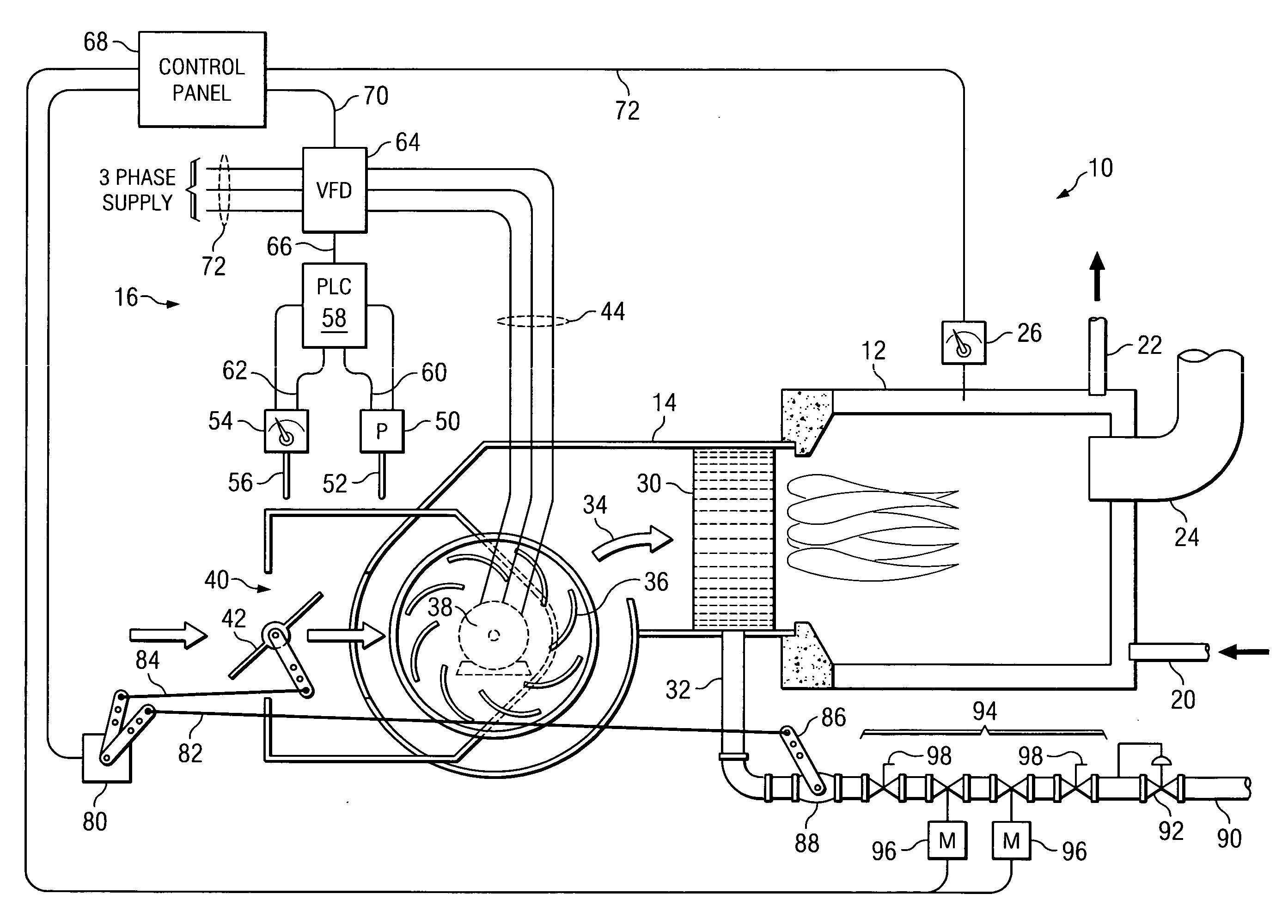
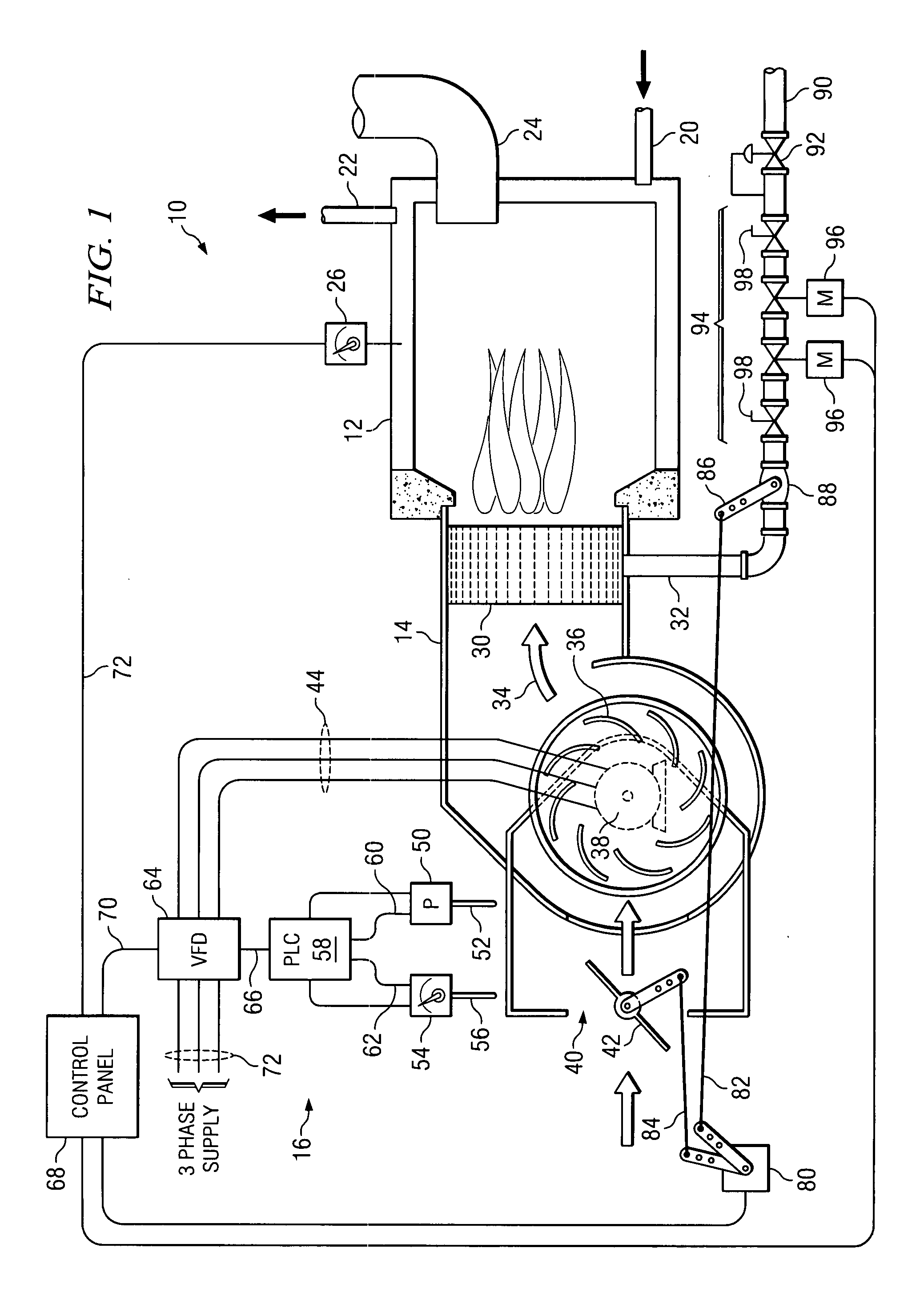
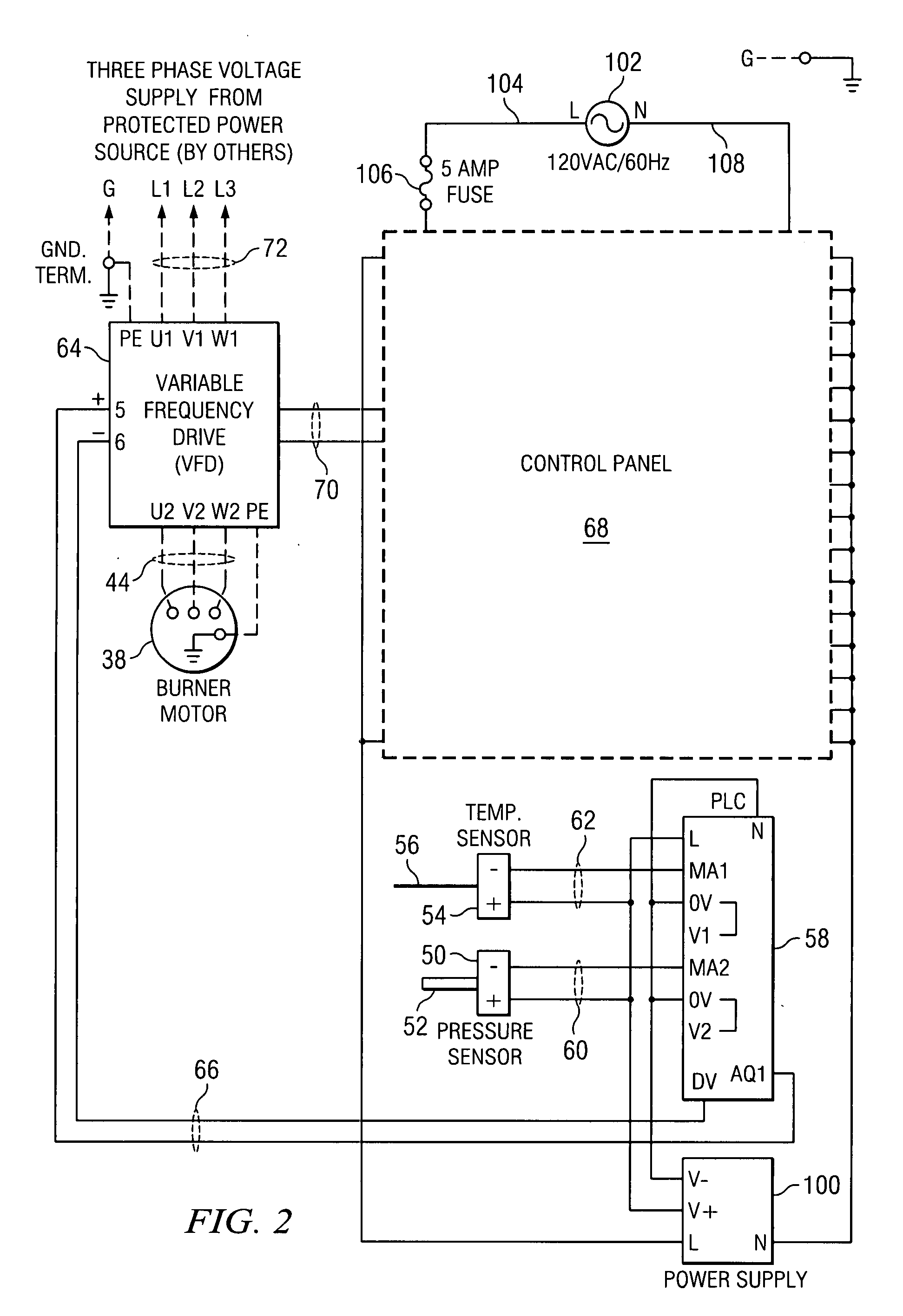
[0033]The embodiment of the present invention described herein is not intended to be limiting but to illustrate the principles and the application of the invention. The present embodiment applies corrections for both combustion air temperature and barometric pressure to an illustrative water heater burner system. As used in the following description, combustion air is the air inlet to the burner, whether it is the ambient air at the inlet to the burner, indoor air ducted to the burner air inlet, or outside air ducted to the burner air inlet. However, the invention may be adapted to use the correction systems individually for temperature or pressure or to either gas-fueled or oil-fueled burners, depending upon the particular application. Further, while the embodiment to be described focuses on the particular control mechanisms that may be embodied in an illustrative water heater system, the present invention is readily adaptable to burners used in other applications such as steam boi...


PUM


Abstract

A method and apparatus that applies corrections to the mass flow rate of combustion air into a gas or oil-fired, forced-draft burner, and thus provides for correcting the air-fuel ratio, by directly measuring the combustion air temperature and/or the barometric pressure of the combustion air, and using these measurements to develop a fan speed drive signal that corrects the volume of air inlet to the burner system without the use of the complex and expensive fully metered control systems, or elaborate feedback systems, or systems that require real-time combustion analysis, and the like.

Description

BACKGROUND OF THE INVENTION[0001]1. Field of the Invention[0002]The present invention generally relates to machine controls and more particularly to the control of combustion in a burner for heating water or other substances by controlling air flow into the burner responsive to changes in physical parameters affecting air and or fuel density.[0003]2. Background and Description of the Prior Art[0004]Burners for machine systems such as water heater boilers for example, generally mix a fuel in gas or liquid form with air to provide a source of heat. Efficient combustion occurs when (a) the ratio of the mass of air to the mass of fuel is held within a small range of values centered on approximately 18-to-1, and (b) sufficient air is mixed with the fuel to ensure combustion of all of the fuel plus some small amount of “excess air.” Generally, sufficient air is provided when the amount of excess air is approximately 15%, which corresponds with an air-fuel ratio of approximately 18-to-1. I...

Claims


Application Information

Patent Timeline
IPC IPC(8): F23N1/02
CPCF23N1/022F23N2033/08F23N2025/19F23N3/082F23N2225/19F23N2233/08
Inventor TOMPKINS, GENEBRENNAN, ALANKUNKLE, JERRY
Owner WEBSTER COMBUSTION TECH LLC
Why Eureka
Try Eureka