Canister

a canister and air technology, applied in the field of canisters, can solve the problems of high cost, high risk of evaporated fuel leakage into the atmosphere, difficulty in installation of the canister in the vehicle, etc., and achieve the effects of reducing air-flow resistance, reducing the risk of activated carbon deterioration, and reducing the risk of leakag

Active Publication Date: 2006-05-23
AISAN IND CO LTD +1
View PDF17 Cites 61 Cited by
  • Summary
  • Abstract
  • Description
  • Claims
  • Application Information

AI Technical Summary

Benefits of technology

[0006]Thus, an object of the present invention is to provide a canister in an evaporated fuel treating equipment for an internal combustion engine, which can solve the above-mentioned problems inherent to the prior art.

Problems solved by technology

The evaporated fuel treating equipment disclosed in JP-A-8-218922 has a complicated configuration and many parts since it requires not only two canisters, that is, the first canister and the second canister, but also a separate pipe line as the second evaporated fuel passage, and accordingly, it is expensive in costs and as well causes a difficulty in installation thereof in a vehicle.
Further, there has been a problem caused a risk of leakage of evaporated fuel to the atmosphere due to break-away of a pipe line.
The evaporated fuel treating equipment disclosed in the JP-A-2002-147297 incorporates a plural kinds of activated carbon which can hardly be distinguished from one another, and has caused a problem of erroneous intermingling of activated carbon.

Method used


Image

  • Canister
  • Canister
  • Canister

Examples


embodiment 1

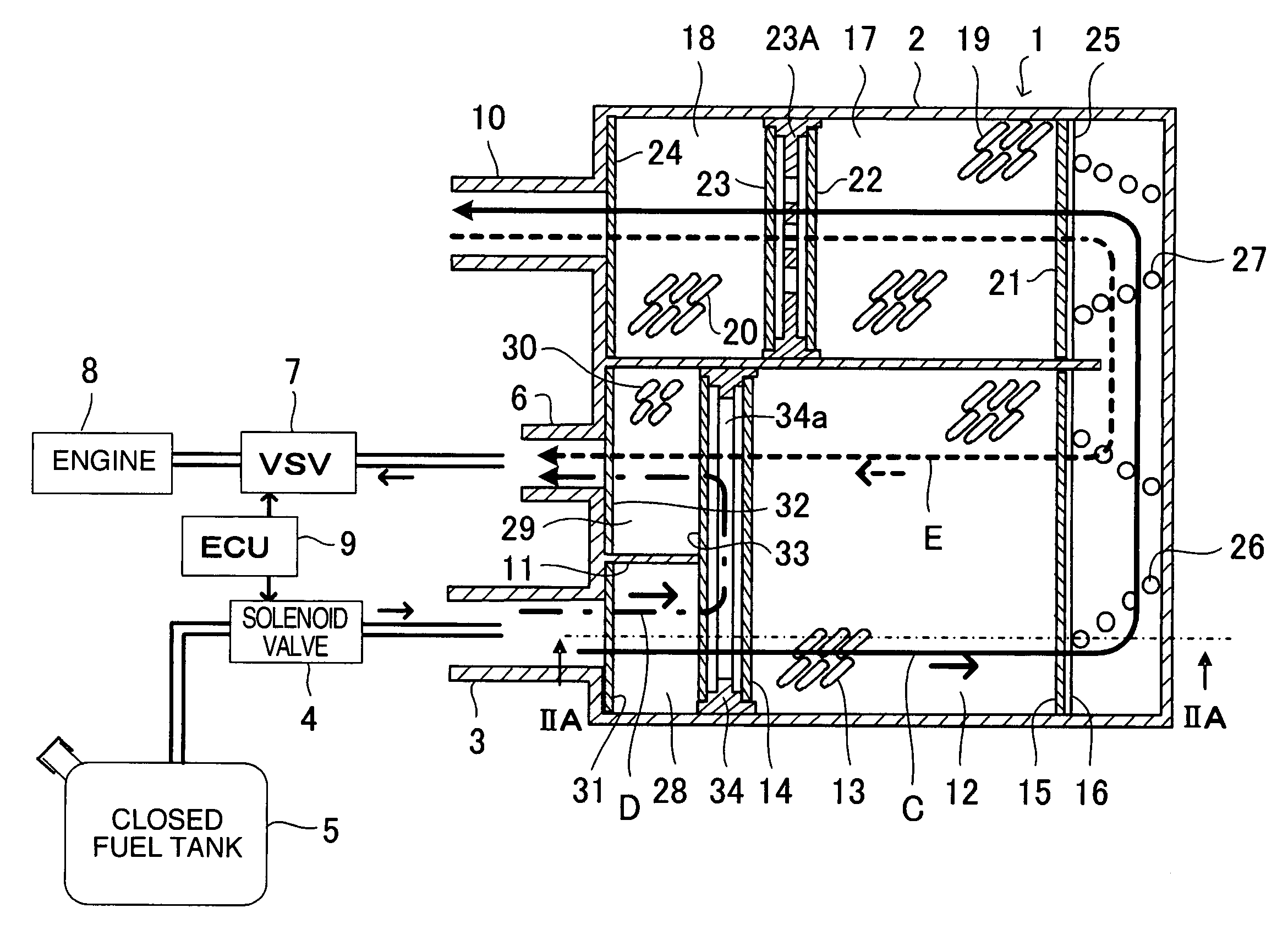
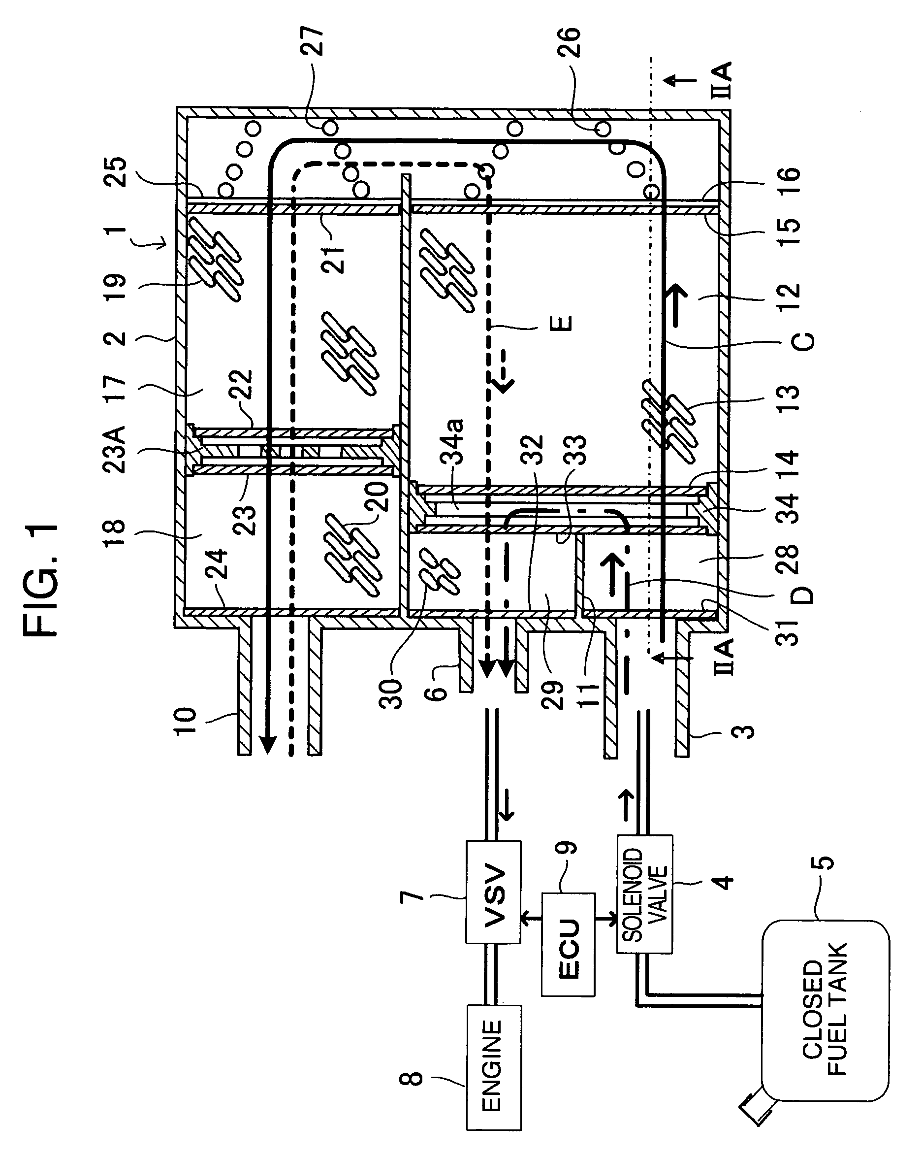
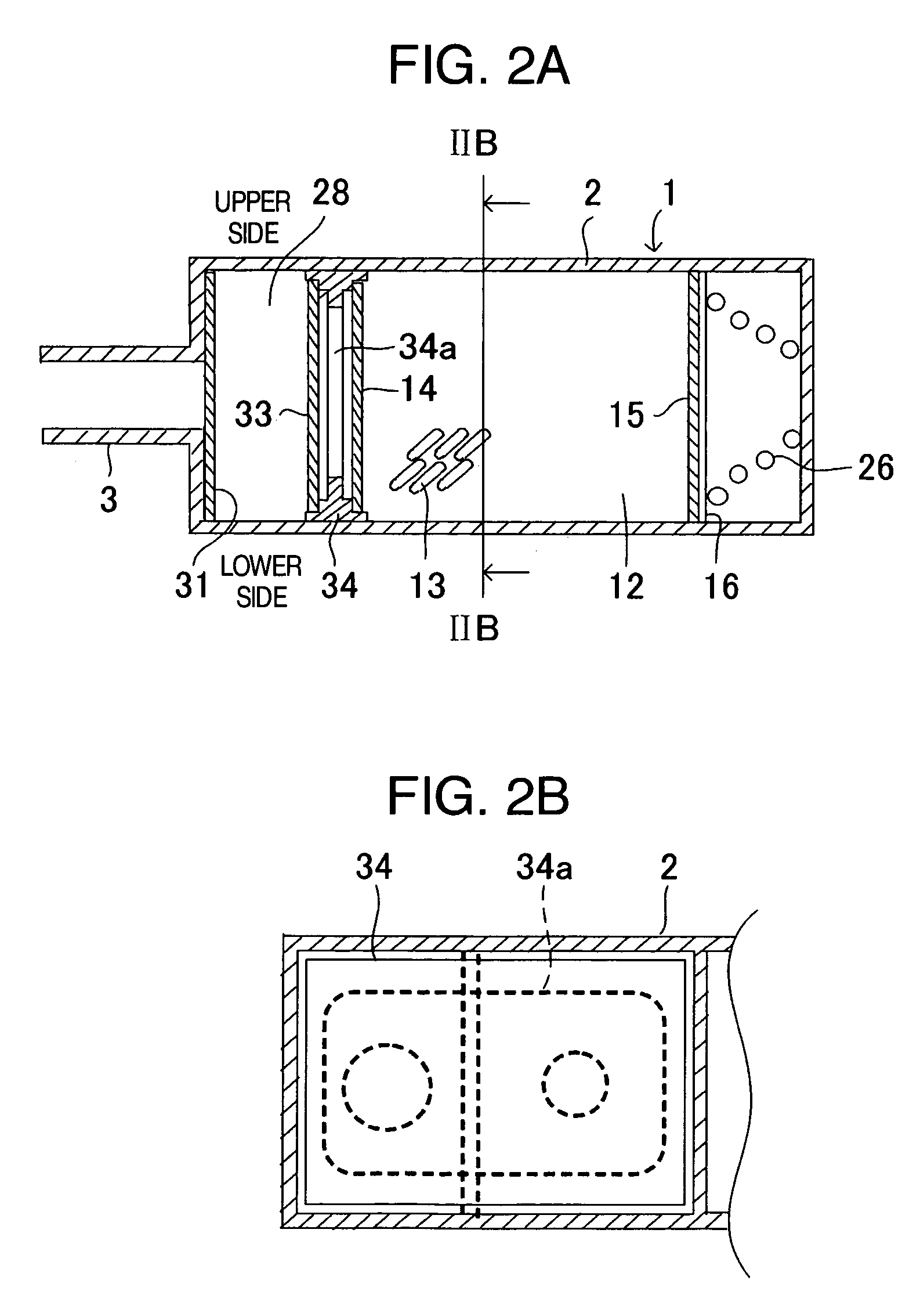
[0041]Referring to FIGS. 1, 2A and 2B which shows an embodiment 1 according to the present invention, in which FIG. 1 is a schematic view illustrating an overall configuration of an evaporated fuel treating equipment in the embodiment 1, in which a canister is shown in a vertical section view, FIG. 2A is a sectional view along line IIA-IIB in FIG. 1, and FIG. 2B is a sectional view line IIB—IIB in FIG. 2A.

[0042]The canister 1 has a casing 2 with a tank port 3, which is communicated with an upper air chamber in a closed fuel tank 5 through the intermediary of a solenoid valve 4. The casing 2 also is provided with a purge port 6, which is connected to an intake passage of an engine 8 through the intermediary of a purge control valve (VSV) 7. An electronic control unit (ECU) 9 controls the solenoid valve 4 and the purge control valve 7. There is also shown an atmospheric port (atmospheric hole) 10.

[0043]Between the tank port 3 and the purge port 6, a partition plate 11 for preventing b...

embodiment 2

[0053]Referring to FIG. 6 which shows an embodiment 2 according to the invention, this embodiment has the same configuration as that of the embodiment 1, except that the activated carbon 30 contained in the second chamber 29 is packed by a filter member 35 wrapping it while the activated carbon 13, 19, 20 are not packed. In order to assembly the packed activated carbon 30 wrapped with the filter member 35 as shown in FIG. 6, the casing 2 is configured such that a cover 2A is finally secured by welding to the right side of the casing 2 as viewed in the figure.

[0054]In this embodiment 2, the same reference numerals are used to denote parts having the same functions as that of those in the embodiment 1 so as to abbreviate the explanation thereof. Further, the arrows showing the flow of the evaporated gas and the like are similar to those of the embodiment 1, and accordingly, which are not shown for the brevity of the figure.

embodiment 3

[0055]Referring to FIGS. 7, 8A and 8B which show an embodiment 3 of the invention, the configuration of the embodiment 3 is the same as that of the embodiment 1, except that the shape of the purge buffer plate 34, in particular, the shape of the passage 34a, is different from that of the embodiment 1. Thus, the same reference numerals are used to denote the same parts as those in the embodiment 1 in order to abbreviate the explanation thereto.

[0056]In this embodiment 3, the passage 34a communicating between the first chamber 28 and the second chamber 29 is located on the upper side of the purge buffer plate 34 in the posture the canister 1 installed in the vehicle, and accordingly, the evaporated gas (vapor) having flown into the first chamber 28 from the tank port 3 can hardly flow into the main adsorbent chamber 12 but can smoothly flow into the second chamber 29.


PUM

PropertyMeasurementUnit
volumeaaaaaaaaaa
volumeaaaaaaaaaa
sizeaaaaaaaaaa

Abstract

A canister comprises a tank port communicated with an upper air chamber in a closed fuel tank, a purge port communicated with an intake passage of an engine, an atmospheric port opened to the atmosphere, and a main adsorbent chamber containing activated carbon, and the canister is further provided with a partition plate between the tank port and the purge port for preventing both ports from being directly communicated with each other, so as to form a first chamber between the main adsorbent chamber and the tank port, and a second chamber between the main adsorbent chamber and the purge port, and a purge buffer plate is further provided in the main adsorbent chamber between the tank port and the purge port, for communicating between the first and second chambers with each other, the first chamber serves as an air chamber containing no activated carbon while the second chamber contains activated carbon. With this configuration, the canister has no external pipe line, the time change in fuel concentration of purged gas during treatment of evaporated fuel from the fuel tank is moderated in order to restrain an engine air-fuel ratio from being abruptly changed, and the operation ability of the engine can be satisfied.

Description

BACKGROUND OF THE INVENTION[0001]The present invention relates to a canister used in an evaporated fuel treating equipment for an internal combustion engine.RELATED ART[0002]There has been well-known such an evaporated fuel treating equipment for an internal combustion engine, comprising a first canister and a second canister for adsorbing evaporated fuel generated from a fuel tank, the canisters being connected in series with each other between an atmospheric port of the first canister and an intake passage of an internal combustion chamber so as to cause air flowing from the atmospheric port to flow through the first canister and the second canister, successively, in order to purge evaporated fuel adsorbed in these canisters, the evaporated fuel and the air being then fed into the intake passage, a first evaporated fuel passage for guiding evaporated fuel generated from the fuel tank during fueling the fuel tank, and a second evaporated fuel passage for guiding evaporated fuel gen...

Claims


Application Information

Patent Timeline
Patent Type & Authority Patents(United States)
IPC IPC(8): F02M33/02
CPCB01D53/0415F02M25/0854B01D53/0446B01D53/0454B01D2253/102B01D2257/702B01D2258/012F02M2025/0881B01D2259/4516B01D2259/4566F02M25/089F02M2025/0863B01D2259/40086
Inventor YAMAUCHI, TOKIONAGAI, TAKASHIHAYAKAWA, MASAMITSUKANEDA, YUKIHIKOIRIYAMA, YOJIRO
Owner AISAN IND CO LTD
Why Eureka
Try Eureka