Cylinder-by-cylinder air-fuel ratio calculation apparatus for multi-cylinder internal combustion engine

a multi-cylinder, air-fuel ratio technology, applied in the direction of electrical control, process and machine control, instruments, etc., can solve the problems of increasing the amount of calculation, increasing the cost, and insufficient resolution of the variations between the cylinders, so as to improve the accuracy of air-fuel ratio control, improve the accuracy, and improve the accuracy

Active Publication Date: 2005-02-03
DENSO CORP
View PDF8 Cites 60 Cited by
  • Summary
  • Abstract
  • Description
  • Claims
  • Application Information

AI Technical Summary

Benefits of technology

The invention has a primary object to provide a cylinder-by-cylinder air-fuel ratio calculation apparatus for a multi-cylinder internal combustion engine in which the complication of modeling is resolved by using a simple model, and a cylinder-by-cylinder air-fuel ratio can be calculated with high accuracy, and to realize an improvement in accuracy of an air-fuel ratio control performed using this cylinder-by-cylinder air-fuel ratio.
In the invention, a model is created in which a sensor detection value of an air-fuel ratio sensor is made one obtained by multiplying a history of a cylinder-by-cylinder air-fuel ratio of an inflow gas in an exhaust collective part and a history of the sensor detection value by specified weights respectively and by adding them, and the cylinder-by-cylinder air-fuel ratio is estimated on the basis of the model. According to the structure as stated above, since the model is used in which attention is paid to the inflow of the gas and the mixture in the exhaust collective part, the cylinder-by-cylinder air-fuel ratio can be calculated which reflects gas exchange behavior in the exhaust collective part. Besides, since the model (autoregressive model) is used in which the sensor detection value is predicted from the past value, differently from the conventional structure using the finite combustion histories (combustion air-fuel ratios), it is not necessary to increase the histories to improve the accuracy. As a result, the complication of modeling is resolved by using the simple model, and the cylinder-by-cylinder air-fuel ratio can be calculated with high accuracy.

Problems solved by technology

However, in the techniques of the above patents, when consideration is given to the fact that the exhausts of the respective cylinders are mixed in the exhaust collective part, the variations between the cylinders cannot be sufficiently resolved, and a further improvement is desired.
However, this requires the air-fuel ratio sensors the number of which is equal to the number of cylinders, and the cost is increased.
However, in this model, the air-fuel ratio in the exhaust collective part is determined by the finite combustion histories (combustion air-fuel ratios), and the histories must be increased in order to improve the accuracy, and there has been a fear that the amount of calculation is increased and the modeling becomes complicated.

Method used


Image

  • Cylinder-by-cylinder air-fuel ratio calculation apparatus for multi-cylinder internal combustion engine
  • Cylinder-by-cylinder air-fuel ratio calculation apparatus for multi-cylinder internal combustion engine
  • Cylinder-by-cylinder air-fuel ratio calculation apparatus for multi-cylinder internal combustion engine

Examples


first embodiment

(First Embodiment)

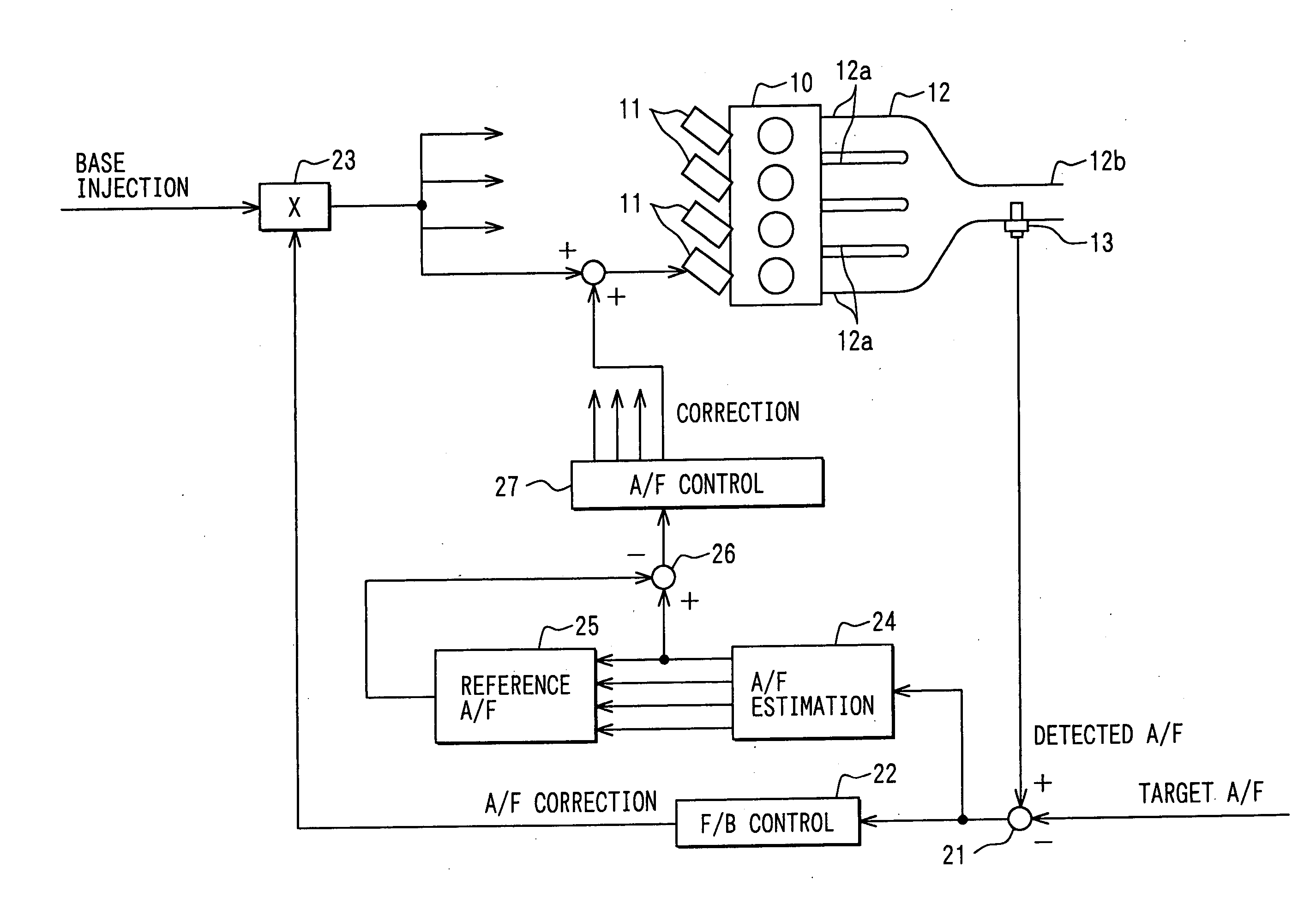
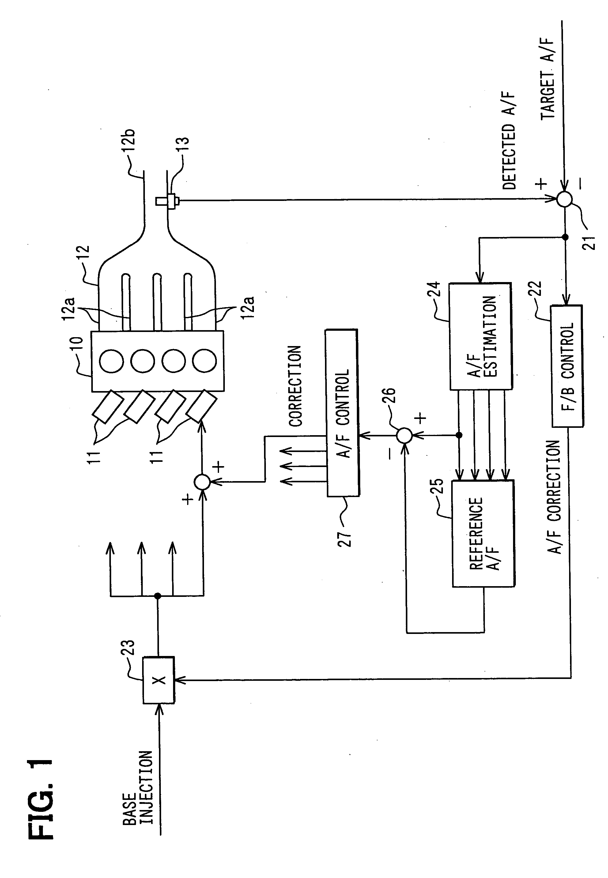
Hereinafter, a first embodiment embodying the invention will be described with reference to the drawings. In this embodiment, an engine control system is constructed for a vehicle-mounted 4-cylinder gasoline engine as a multi-cylinder internal combustion engine. In the control system, an engine controlling electronic control unit (hereinafter referred to as an engine ECU) is made the center, and the control of a fuel injection amount, the control of an ignition timing and the like are carried out. First, the main structure of this control system will be described with reference to FIG. 1.

In FIG. 1, electromagnetic driven fuel injection valves 11 are attached to respective cylinders in the vicinities of intake ports of an engine 10. When fuel is injected and supplied to the engine 10 from the fuel injection valves 11, in the intake port of each of the cylinders, intake air and the injected fuel by the fuel injection valve 11 are mixed to form a mixed gas, and thi...

second embodiment

(Second Embodiment)

In the first embodiment, the cylinder-by-cylinder air-fuel ratio is estimated on the basis of the detection values of the A / F sensor 13, and the cylinder-by-cylinder air-fuel ratio control is performed so as to eliminate the variations in air-fuel ratios between the cylinders on the basis of the cylinder-by-cylinder air-fuel ratio (estimated value). However, according to an engine operation state, there is a case where the estimation of the cylinder-by-cylinder air-fuel ratio becomes difficult. In the case where the cylinder-by-cylinder air-fuel ratio cannot be estimated, the cylinder-by-cylinder air-fuel ratio control cannot be performed, and therefore, there is a fear that the variations in air-fuel ratios between the cylinders cannot be resolved. For example, the situation as stated above occurs immediately after the starting of an engine, or at the time of high revolution or low load operation. In this embodiment, the variations in air-fuel ratios between the...

third embodiment

(Third Embodiment)

There is conventionally known an evaporated fuel discharge apparatus in which an evaporated fuel generated in a fuel tank is once adsorbed by a canister (fuel adsorbing apparatus), and then, the fuel is discharged (purged) to an engine intake system and is burned in a combustion chamber. In a control system provided with this apparatus, it is proposed to correct a fuel injection amount by a fuel injection valve (fuel injection device) according to a discharge amount (purge amount) of the evaporated fuel. However, in the case of a multi-cylinder internal combustion engine, there is a problem that a purge amount distributed to each cylinder varies due to difference in shape, length and the like of an intake passage from the canister to the combustion chamber, and as a result, air-fuel ratio F / B control becomes unstable.

In JP-A-2001-173485, a purge distribution rate between cylinders is previously considered, and a purge distribution correction coefficient is set, ...


PUM


Abstract

An air-fuel ratio deviation calculated by an air-fuel ratio deviation calculation part is inputted to a cylinder-by-cylinder air-fuel ratio estimation part. A cylinder-by-cylinder air-fuel ratio is estimated in the cylinder-by-cylinder air-fuel ratio estimation part. In the cylinder-by-cylinder air-fuel ratio estimation part, attention is paid to gas exchange in an exhaust collective part of an exhaust manifold, and a model is created. In this model, a detection value of an A / F sensor is obtained by multiplying histories of the cylinder-by-cylinder air-fuel ratio of an inflow gas in the exhaust collective part and histories of the detection value of the A / F sensor by specified weights respectively and by adding them. The cylinder-by-cylinder air-fuel ratio is estimated on the basis of the model.

Description

CROSS-REFERENCE TO RELATED APPLICATION This application is based on Japanese Patent Application No. 2003-283143 filed on Jul. 30, 2003, Japanese Patent Application No. 2003-427064 filed on Dec. 24, 2003 and Japanese Patent Application No. 2004-138027 filed on May 7, 2004, the disclosures of which are incorporated herein by reference. FIELD OF THE INVENTION The present invention relates to a cylinder-by-cylinder air-fuel ratio calculation apparatus for a multi-cylinder internal combustion engine, and particularly to a technique in which an air-fuel ratio sensor installed in an exhaust collective part of a multi-cylinder internal combustion engine is used, and an air-fuel ratio for each cylinder is suitably calculated on the basis of a detection value of the sensor. BACKGROUND OF THE INVENTION Conventionally, there is proposed an air-fuel ratio control apparatus in which an exhaust air-fuel ratio of an internal combustion engine is detected, and a fuel injection a mount is controll...

Claims


Application Information

Patent Timeline
Patent Type & Authority Applications(United States)
IPC IPC(8): F02M25/08F02D41/00F02D41/14F02D41/34F02D45/00
CPCF02D41/0032F02D41/008F02D41/1454F02D41/1456F02D41/1458F02D41/1479F02D2200/0402F02D41/2454F02D41/2477F02D2041/1433F02D2041/1437F02D2041/2027F02D41/1481
Inventor IKEMOTO, NORIAKIIIDA, HISASHI
Owner DENSO CORP
Why Eureka
Try Eureka