Delivery System With Profiled Sheath Having Balloon-Oriented Position

a delivery system and balloon-oriented technology, applied in balloon catheters, medical science, surgery, etc., can solve problems such as vessel and achieve the effect of reducing the incidence of sheath catching and minimizing any adverse effects of sheaths

Inactive Publication Date: 2009-04-30
CAPPELLA INC
View PDF21 Cites 88 Cited by
  • Summary
  • Abstract
  • Description
  • Claims
  • Application Information

AI Technical Summary

Benefits of technology

[0008]Embodiments of the present invention serve to minimize any adverse effects of the sheath on either the positioning of the delivery system or the vessel itself. The sheath is made with a profile and leading edge that, as the delivery system is distally moved through a vessel, does not interfere with positioning. The profiled sheath also reduces incidences of the sheath catching on lesions in the vessel. Further, an initiation slit provided on the sheath is oriented with respect to a balloon portion of the delivery system.

Problems solved by technology

There have been issues, however, with the sheath having an adverse effect on the vessel as the delivery system is positioned.

Method used


Image

  • Delivery System With Profiled Sheath Having Balloon-Oriented Position
  • Delivery System With Profiled Sheath Having Balloon-Oriented Position
  • Delivery System With Profiled Sheath Having Balloon-Oriented Position

Examples


Embodiment Construction

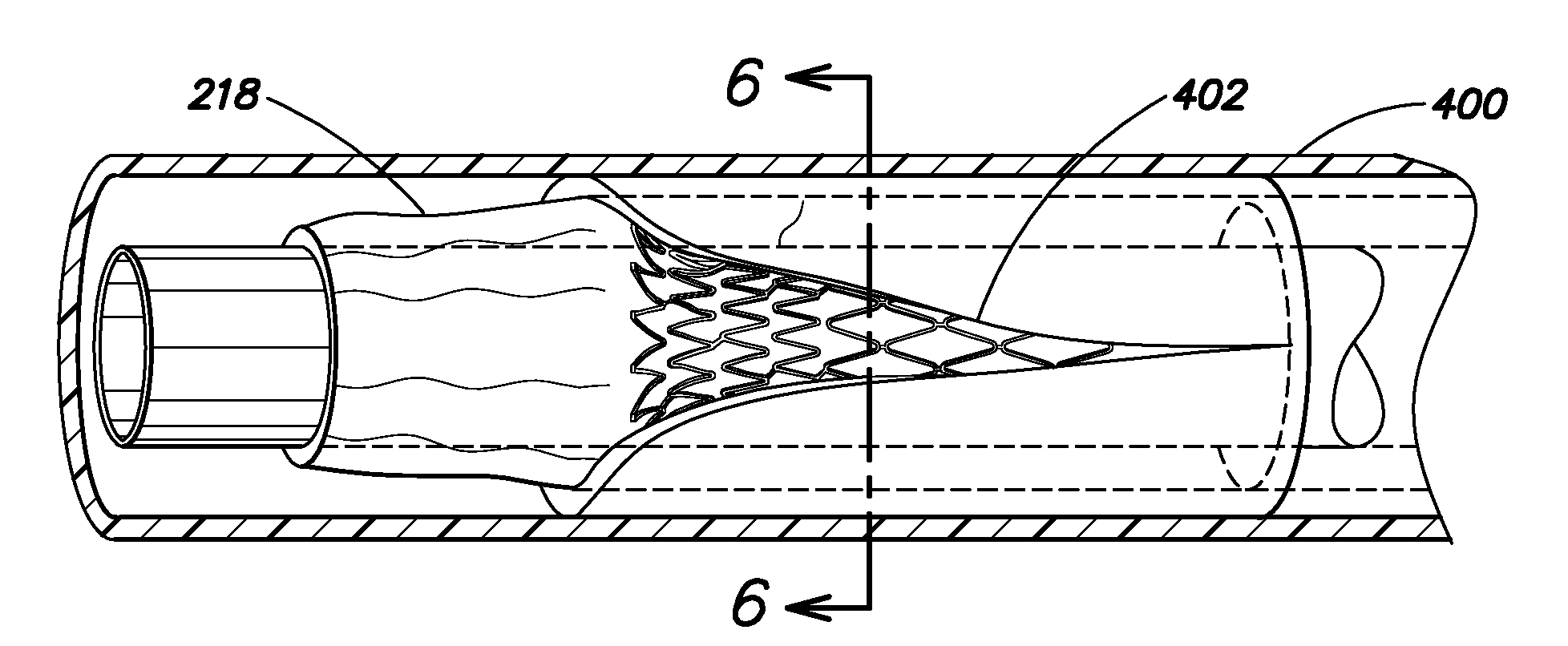
[0036]The present invention is directed to a sheath that is profiled, i.e., shaped, to reduce instances of interference between a distal edge of the sheath and a vessel and / or any lesion or lesions that might be present in the vessel. Embodiments of the sheath and its implementation will be described below in more detail.

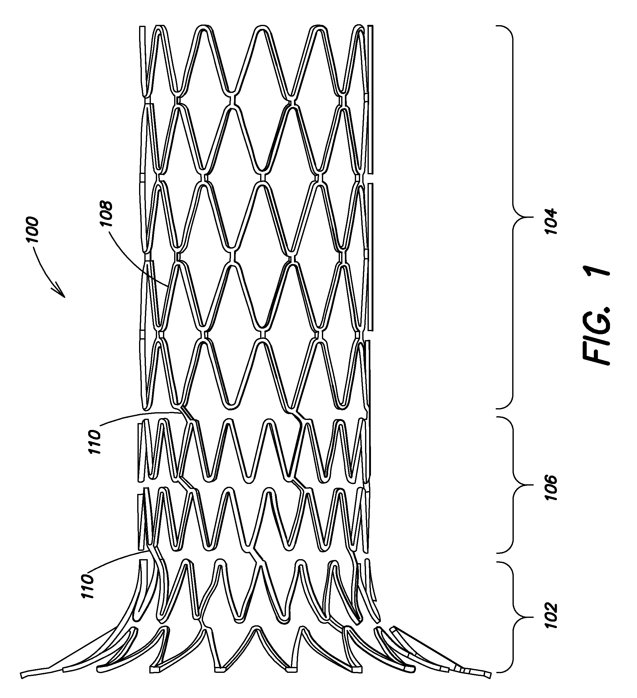
[0037]Reference is now made to FIG. 1, which illustrates a schematic view of a device 100, for example, an ostial protection device as described in co-pending U.S. application Ser. No. 11 / 252,224 filed Oct. 17, 2005 for “Segmented Ostial Protection Device,” and which is herein incorporated by reference in its entirety. It should be noted that the present description is with reference to an ostial protection device for purposes of explanation only. The claims are not limited to systems with medical devices intended for insertion at an ostium.

[0038]The device 100 includes a cap or flared portion 102, an anchor portion 104, and an articulating portion 106. The anchor p...


PUM

PropertyMeasurementUnit
lengthaaaaaaaaaa
temperatureaaaaaaaaaa
pressureaaaaaaaaaa

Abstract

A delivery system for delivering a self-expanding medical device such as a stent. The delivery system includes a sheath profiled or shaped to reduce instances of interference between a distal edge of the sheath and a vessel or with any lesion or lesions that might be present in the vessel. The sheath is formed by modifying a cylinder of sheath material to include three portions and an initiation slit that controls the rupturing of the sheath to facilitate delivery of the medical device. The initiation slit is positioned on the delivery system with respect to a configuration of a balloon portion of the system.

Description

RELATED APPLICATIONSFIELD OF THE INVENTION[0001]The present invention relates to a delivery system for a self-expanding medical device. More particularly, the delivery system is provided with a profiled sheath allowing for better system positioning of the medical device and which has an initiation slit oriented with respect to a balloon portion of the delivery system.BACKGROUND OF THE INVENTION[0002]As is known, treatment of vascular blockages due to any one of a number of conditions, such as arteriosclerosis, often involves balloon dilatation and treatment of the inner vessel wall by placement of a stent. The stent is positioned to prevent restenosis of the vessel walls after the dilatation. Drug eluting stents are now available where medicine is delivered to the vessel wall to also help reduce the occurrence of restenosis.[0003]These stents, i.e., tubular prostheses, typically fall into two general categories of construction. The first category of prosthesis is made from a materia...

Claims


Application Information

Patent Timeline
Patent Type & Authority Applications(United States)
IPC IPC(8): A61M25/10A61M25/16A61F2/958
CPCA61F2/958A61F2/97A61F2250/0039A61M25/1002Y10T29/49826A61F2002/9583A61M25/1029A61M2025/107A61M25/1038
Inventor SLATTERY, DAVIDKELLY, DAMIANO'CONNOR, THERESEKERINS, JOSEPHGILMORE, MICHAELSTECKEL, MARK
Owner CAPPELLA INC
Why Eureka
Try Eureka