Vehicle air-conditioning system

a technology of vehicle air conditioner and air conditioner, which is applied in the direction of refrigeration components, compression machines with several condensers, light and heating apparatus, etc., can solve the problems of not being able to restart operation, plurality of expansion valves require more manufacturing costs, and the plurality of expansion valves requires more manufacturing costs. , to achieve the effect of less hea

Inactive Publication Date: 2009-05-07
HONDA MOTOR CO LTD
View PDF16 Cites 37 Cited by
  • Summary
  • Abstract
  • Description
  • Claims
  • Application Information

AI Technical Summary

Benefits of technology

[0020]By using the exhaust gas from the fuel cell as the fluid which exchanges heat with the refrigerant, it is possible to prevent the occurrence of the dew condensation and a freeze of the dew condensation water at the first evaporator. Because as a temperature of the exhaust gas from the fuel cell increases with increasing in a temperature of the fuel cell, the second evaporator mainly absorbs heat and the first evaporator absorbs less heat. Also, there is no need to provide a heat source to exchange heat with the second evaporator because heat of the exhaust gas from the fuel cell can be reused as it is.

Problems solved by technology

However, in the prior art vehicle air-conditioning system described in JP 10-100662 A, when heating operation is performed in succession, and especially when a temperature of an outside air is low, a problem arises that a dew condensation occurs at the evaporator by which the air for air-conditioning supplied to the front seat passes, and that when a dew condensation water is frozen at the evaporator, the operation can not be restarted until the dew condensation water is melted.
As a result, because much refrigerant flows through another evaporator while few refrigerant flows through one evaporator, a problem arises that enough heating capacity can not be obtained at one evaporator.
That is, being provided with a plurality of the expansion valves requires more manufacturing cost than that of being provided with only one expansion valve.

Method used


Image

  • Vehicle air-conditioning system
  • Vehicle air-conditioning system
  • Vehicle air-conditioning system

Examples


first embodiment

1. Configuration of First Embodiment

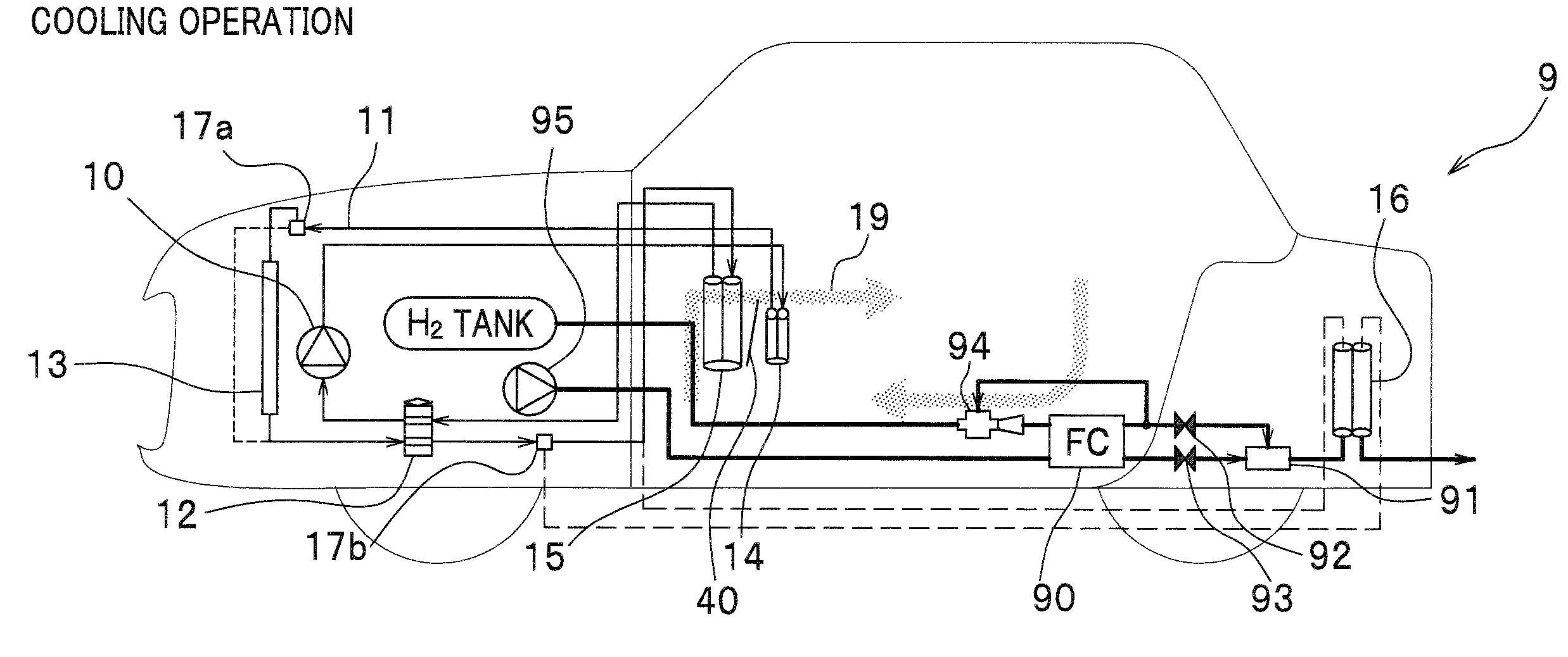
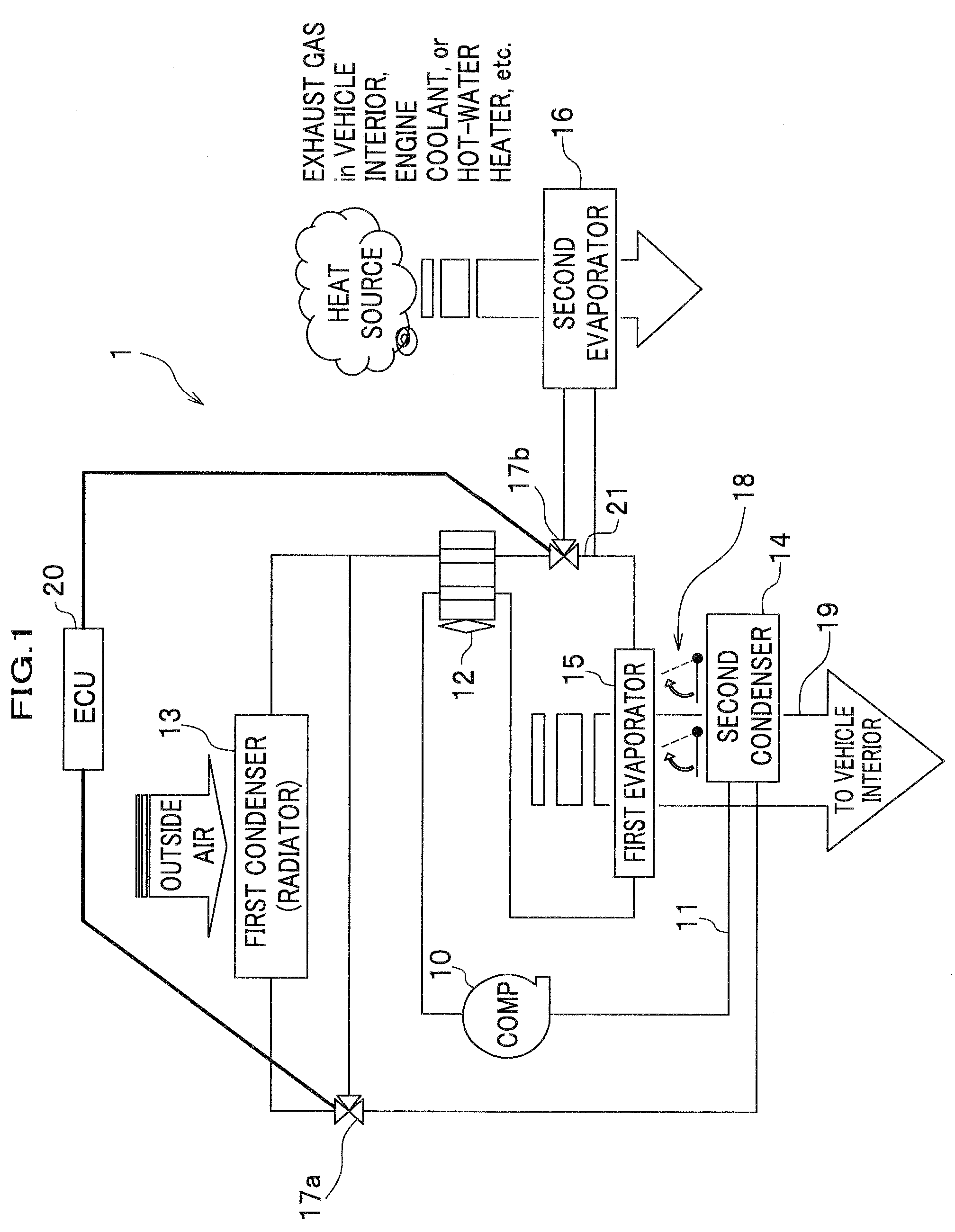
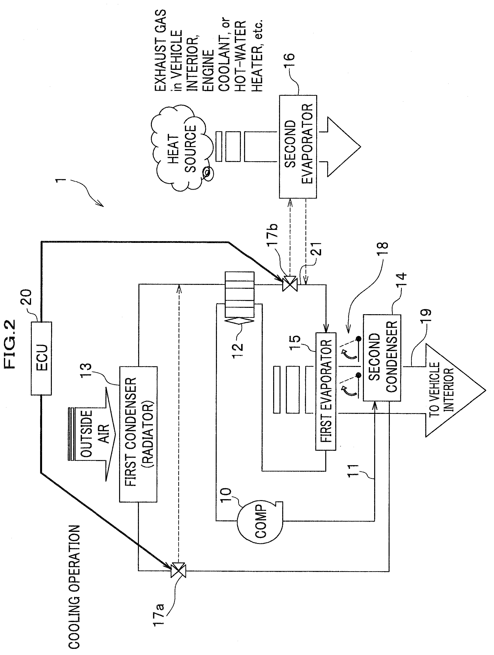
[0032]First, with reference to FIG. 1, a configuration of a first embodiment of the vehicle air-conditioning system according to the present invention will be explained. FIG. 1 is a block diagram of the first embodiment of the vehicle air-conditioning system according to the present invention. Hereinafter, the first embodiment of the vehicle air-conditioning system according to the present invention will be referred to as a vehicle air-conditioning system 1.

[0033]The vehicle air-conditioning system 1 includes a compressor 10 to discharge a compressed high-pressure gas as a refrigerant; a pipe 11 to circulate the refrigerant discharged from the compressor 10; a plurality of heat exchangers (condenser, evaporator) provided at the pipe 11 to exchange heat with an air for air-conditioning; and an automated expansion valve 12 provided with the pipe 11 to expand the refrigerant. Therefore, the high-pressure gas discharged from the compressor 10 as the r...

second embodiment

3.1 Second Embodiment of Vehicle Air-Conditioning System

[0046]First, with reference to FIG. 5A and FIG. 5B, a second embodiment of the vehicle air-conditioning system according to the present invention will be explained. FIG. 5A and FIG. 5B are diagrams showing a configuration of the second embodiment of the vehicle air-conditioning system and circulation paths of the air for air-conditioning in cooling operation and heating operation. Hereinafter, the second embodiment of the vehicle air-conditioning system according to the present invention will be referred to as a vehicle air-conditioning system 5.

[0047]With reference to FIG. 5A and FIG. 5B, the vehicle air-conditioning system 5 has a configuration in which the second condenser 14 of the vehicle air-conditioning system of the first embodiment according to the present invention is replaced with a second condenser including a pump 50 to discharge a hot water, and a pipe 51 in which the hot water circulates. And, the pipe 51 has a f...

third embodiment

3.2 Third Embodiment of Vehicle Air-Conditioning System

[0055]Next, with reference to FIG. 6A and FIG. 6B, a third embodiment of the vehicle air-conditioning system according to the present invention will be explained. FIG. 6A and FIG. 6B are diagrams showing a configuration of the third embodiment of the vehicle air-conditioning system and circulation paths of the air for air-conditioning in cooling operation and heating operation. Hereinafter, the third embodiment of the vehicle air-conditioning system according to the present invention will be referred to as a vehicle air-conditioning system 6.

[0056]With reference to FIG. 6A and FIG. 6B, the vehicle air-conditioning system 6 uses an engine coolant as a heat source in heating operation. In addition, in heating operation, a heat of the engine coolant from an engine 60 is absorbed at a second evaporator 61. And, the heat of the engine coolant absorbed at the second evaporator 61 is conducted to the first evaporator 15 via the refrige...


PUM


Abstract

The present invention provides a vehicle air-conditioning system in which an air for air-conditioning is cooled at a first evaporator, is heated at a condenser, and is supplied to a vehicle interior in heating operation. The object of the present invention is to suppress a dew condensation at the first evaporator to prevent a freeze of the dew condensation water even if the temperature of the air for air-conditioning introduced from the outside of the vehicle is low. The above object is achieved by disposing a second evaporator between an automated expansion valve to decompress the refrigerant exhausted from a compressor and the first evaporator so as to reduce the absorbed heat at the first evaporator.

Description

CROSS REFERENCE TO RELATED APPLICATIONS[0001]The present application claims benefit of the filing date of Japanese Patent Application No. 2007-287970 filed on Nov. 6, 2007 which is incorporated herein by reference.FIELD OF THE INVENTION[0002]The present invention relates to suppression of dew condensation in heating operation of a vehicle air-conditioning system.DESCRIPTION OF THE RELATED ART[0003]As a prior art vehicle air-conditioning system, JP 2992779 B2 discloses a vehicle air-conditioning system in which an air-conditioning operation is changed between cooling operation and heating operation by actuating a four-way valve so as to reverse a flow direction of a refrigerant in a pipe and to reverse roles of an evaporator (heat exchanger for heat-absorbing) and a condenser (heat exchanger for heat-radiating) (see [0016]-[0020]). In this vehicle air-conditioning system, the refrigerant is circulated by expanding a high-pressure gas discharged from a compressor with an electric expa...

Claims


Application Information

Patent Timeline
Patent Type & Authority Applications(United States)
IPC IPC(8): B60H1/32B60H1/00F25B49/00F25B7/00F25B41/04
CPCB60H1/323B60H2001/00949B60H2001/3283F25B5/04F25B6/04F25B47/006F25B2341/0011F25B2341/0683F25B2400/0403F25B2400/0409F25B2600/21F25B2600/2513F25B2700/21175B60H1/00921B60H2001/3252B60H2001/3298
Inventor ESAKI, HIDENORI
Owner HONDA MOTOR CO LTD
Why Eureka
Try Eureka