Method of producing initial components for saw blades or saw bands

a technology of initial components and saw blades, which is applied in the direction of manufacturing tools, sawing tool dressing arrangements, metal sawing tool making, etc., can solve the problems of high cost of cutting materials, and low production efficiency, and achieves reduced installation effort, high quality, and automatic welding process

Inactive Publication Date: 2009-05-07
BOEHLER UDDEHOLM PRECISION STRIP GMBH
View PDF0 Cites 14 Cited by
  • Summary
  • Abstract
  • Description
  • Claims
  • Application Information

AI Technical Summary

Benefits of technology

[0014]Thereby, a method is provided in which two preforms for saw blades or saw bands can be manufactured out of two carrier bands and one strip of cutting material only by alternating laser beam or electron beam welding and laser beam or electron beam separating. Therefore a additional individual separating cut for separating the pre-forms is not necessary.
[0015]This method can be processed fully automatically and continuously and needs no manual action. Therefore the method is very cheap and provides additional preforms with a continuously high quality.
[0016]The laser or electron beam welding has in comparison with the conventional welding or brazing the advantage that only a very locally limited heat input occurs in the material and therefore a warping is avoided. Furthermore no brazing is necessary and the welding process can be automated.
[0017]Because welding and separating is done in the direct neighbourhood, the installation effort is reduced because the clamping and transport devices for the carrier bands and the strips arranged in between have only to be provided once.
[0018]Additionally the alternating welding and separating method reduces temperature induced warping because a heat input occurs once and only locally.

Problems solved by technology

The above described cutting of the cutting contour is related to a high lost of expensive cutting material because the material of the cut space between the teeth is lost.

Method used


Image

  • Method of producing initial components for saw blades or saw bands
  • Method of producing initial components for saw blades or saw bands
  • Method of producing initial components for saw blades or saw bands

Examples


Embodiment Construction

[0043]In the following preferred embodiments of the present invention will be explained in detail with reference to the figures.

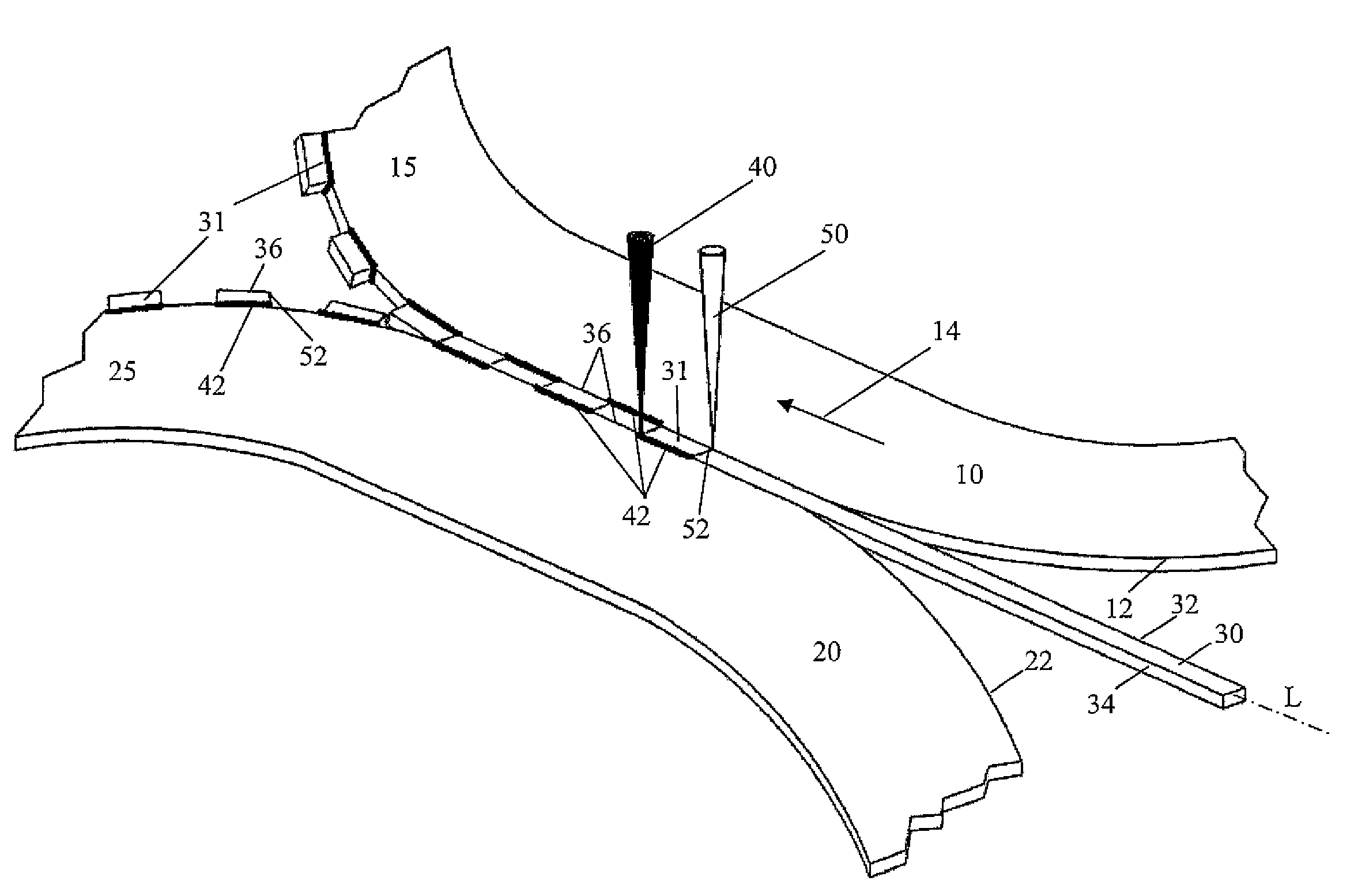
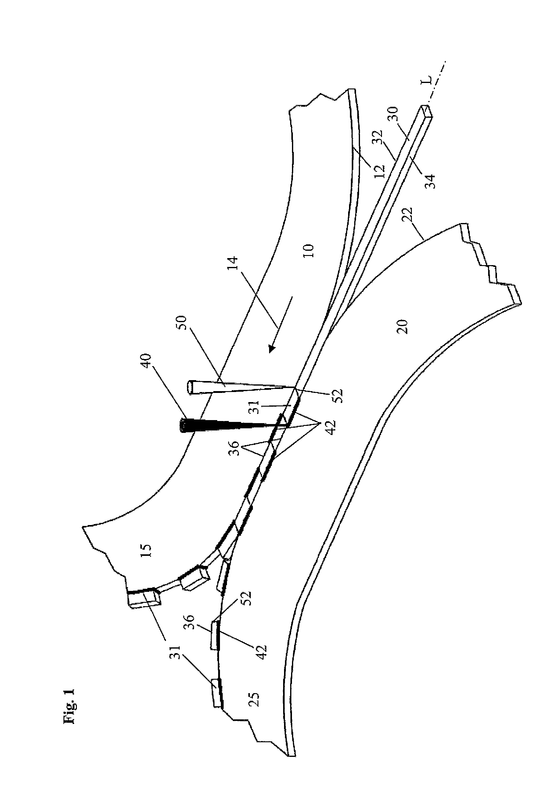
[0044]FIG. 1 shows the method for manufacturing of two preforms 15, 25 for saw blades respectively saw bands.

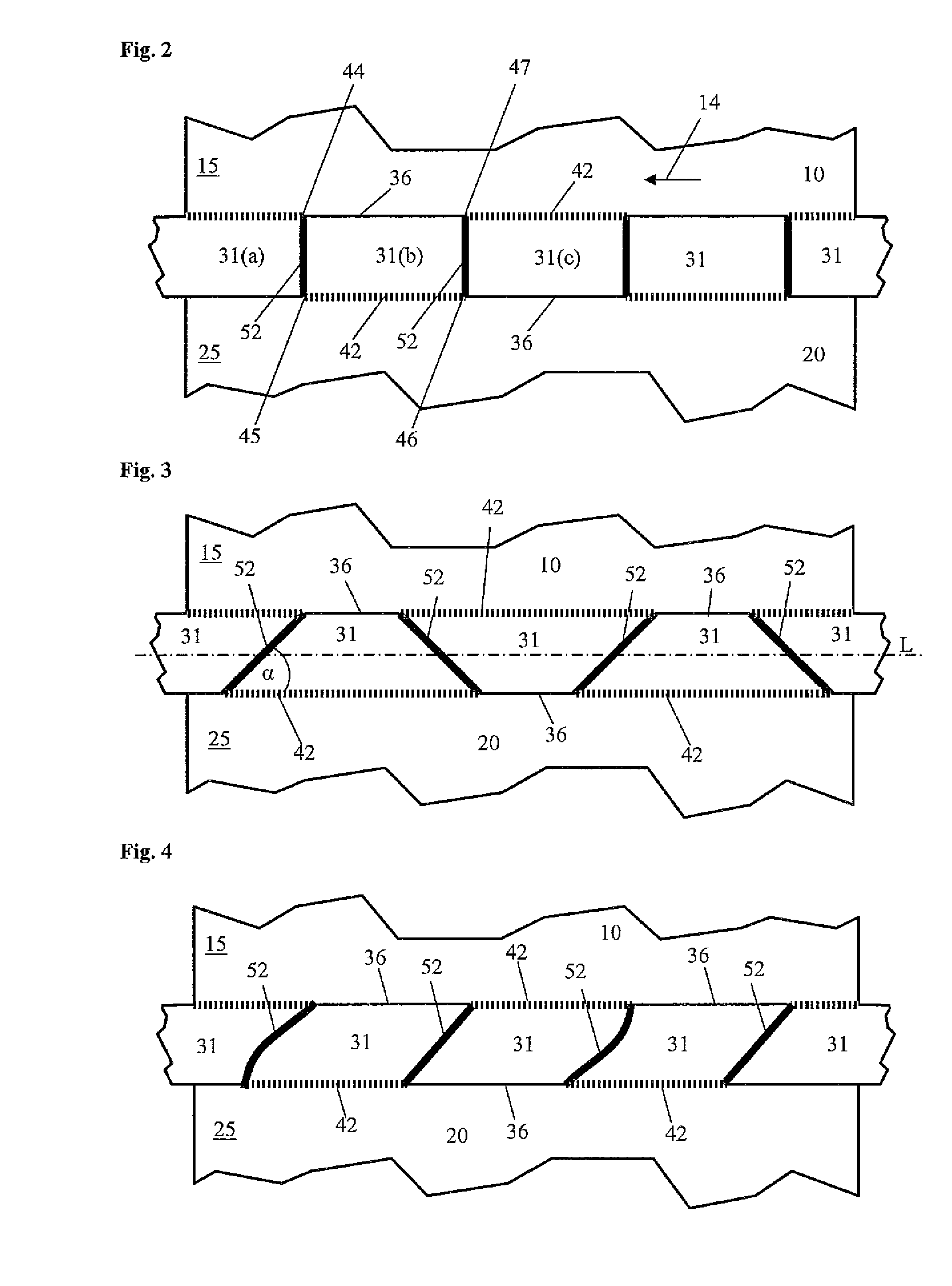
[0045]First of all a strip 30 of a cutting material for a cutting edge of saw blades respectively saw bands is arranged between the edge 12 of a first carrier band 10 and the edge 22 of a second carrier band 20. The carrier bands 10, 20 respectively the strip 30 comprise preferably a rectangle cross section.

[0046]The arrangement of the carrier bands 10, 20 and strips 30 clamped in between will be moved under the cutting respectively welding facility as indicated by the arrow 12, which on the one side cuts the strips 30 in segments 31 and welds these segments 31 or parts of the strip 30 to the carrier bands 10, 20, respectively.

[0047]For cutting and also for welding the laser beams 40, 50 are preferably used. The laser beams 40, 50 can be used under u...


PUM

PropertyMeasurementUnit
thicknessaaaaaaaaaa
shapeaaaaaaaaaa
elasticaaaaaaaaaa

Abstract

The present invention relates to a method for manufacturing of preforms (15, 25) for saw blades respectively saw bands, comprising the following steps (a) arranging a strip (30) of a cutting material for a cutting edge of saw blades respectively saw bands without any play between the edges (12, 22) of a first carrier band (10) and a second carrier band (20); (b) guiding of a laser or electron beam (40) along a first edge (32) of the strip (30) for welding part per part of the first carrier band (10) to the strip (30), wherein regions (36) along the first edge (32) of the strip (30) remain unwelded; (c) guiding of a laser or electron beam (40) along a second edge (34) of the strip (30) for welding part per part of the second carrier band (20) to the strip (30), wherein regions (36) along the second edge (34) of the strip (30) remain unwelded; and (d) guiding a laser, water or electron beam (50) between the first edge (32) and the second edge (34) of the strip (30) or the second edge (34) and the first edge (32) of the strip (30) for separating of the strip (30) into segments (31).

Description

1. FIELD OF INVENTION[0001]The present invention relates to a method for manufacturing of a preform for producing saw blades respectively saw bands.2. BACKGROUND OF THE INVENTION[0002]As a preform for manufacturing of saw blades respectively saw bands with hard and wear-resistant regions of the tip of the teeth a composite steel blade or a composite steel band (bimetal band) is generally used. A strip of a cutting material is welded or braised to the edge of a tough, elastic carrier band made of steel.[0003]Since this preform consists of different materials it is also known under the name bimetal band or bimetal blade. Because of the usage of for example tool steel respectively other cutting materials the later regions of the tip of the teeth of the thereof manufactured saw blades respectively saw bands comprise a higher wear resistance and the saw blade or band reaches a higher lift time.[0004]For the manufacturing of the saw blade or band a tooth profile respectively a tooth conto...

Claims


Application Information

Patent Timeline
Patent Type & Authority Applications(United States)
IPC IPC(8): B23D65/00B23K26/36
CPCB23D65/00
Inventor AHORNER, LEANDER
Owner BOEHLER UDDEHOLM PRECISION STRIP GMBH
Why Eureka
Try Eureka