Encapsulated ceramic composite armor

a composite armor and ceramic technology, applied in the field of composite armor, can solve the problems of kinking fibers around the penetration cavity, too heavy and expensive for lighter fighting vehicles or transports, and inability to protect vehicle occupants from many common ballistic and blast threats,

Inactive Publication Date: 2009-05-07
INTPROP HLDG
View PDF99 Cites 113 Cited by
  • Summary
  • Abstract
  • Description
  • Claims
  • Application Information

AI Technical Summary

Benefits of technology

[0012]The present invention thus provides, in one aspect, a composite armor that includes a disruptive layer including a sheet of adjoining polygonal ceramic tiles encased by a retaining polymer, the ceramic tiles having a non-spherical deflecting front surface, and a backing layer adjacent to the disruptive layer. The backing layer may be formed of a polymer encased reinforcement including steel wires, metal bonded steel wires, ceramic or glass fibers, or a metallic sheet. The composite armor may also include a spalling layer adjacent to the disruptive layer, wherein the spalling layer includes a polymer-encased reinforcement. Embodiments of the composite armor provide a disruptive layer than has an areal density less than 50% of the areal density of rolled homogeneous armor given by the density of rolled homogeneous armor and the depth of penetration by a specific ballistic projectile.

Problems solved by technology

However, while “Chobham armor” is well suited for use placement on a main battle tank, it is too heavy and expensive for use on lighter fighting vehicles or transports.
However, relatively simple fiber-based composite armors have difficulty protecting vehicle occupants against many common ballistic and blast threats.
Studies indicate that sharp-nosed projectiles tend to move the fibers within the composite laterally away from the advancing projectile, resulting in kinked fibers around the penetration cavities but with little energy absorption.
During impact, the projectile is blunted and cracked or shattered by the hard ceramic face.
Fragmentation and comminution are produced in the ceramic and the projectile, resulting in fine ceramic rubble traveling with the projectile.
Unfortunately, during this process, the armor system is typically damaged.
However, strong stress waves can still damage tiles adjacent to the impacted tile by propagating through the edges of the impacted tile and into adjacent tiles.
Ceramic tiles can also be damaged by the deflection and vibration of the backing plate.
In addition, impact from the lateral displacement of material during ceramic fracturing can crush and damage adjacent tiles.
However, these examples do not provide guidance on how to provide composite armor that achieves an areal density well below the areal density of rolled homogeneous armor or similar steel armor solutions needed to defeat a ballistic threat.
For example, in Lucuta et al., the thickness of the ceramic tile will always be above the critical limit needed to defeat a projectile, resulting in the presence of excess material that will result in increased areal density.
These forms of armor have not ensured that the tile thickness and therefore the areal density is not excessive without sacrificing ballistic performance.

Method used


Image

  • Encapsulated ceramic composite armor
  • Encapsulated ceramic composite armor
  • Encapsulated ceramic composite armor

Examples


example 1

Benchmarking .50 Cal APIT

[0099]Penetrating power of the projectile was determined by using rolled homogenous armor (RHA) and aluminum T6061 specimen. In the case of three RHA, 6×6 inch and 0.5 inch thick plates were stacked to produce 1.5 inch thick test piece. The panel was shot three times. The depth of penetration was measured. The depth when converted to areal density corresponded to about 50 lbs / ft2. In the case of aluminum, two cylinders of 3.5 inch and 2 inch thick were joined to produce a 4 inch deep sample. From measured depth of penetration, equivalent areal density for comparison was about 46 lbs / ft2.

Armor Test

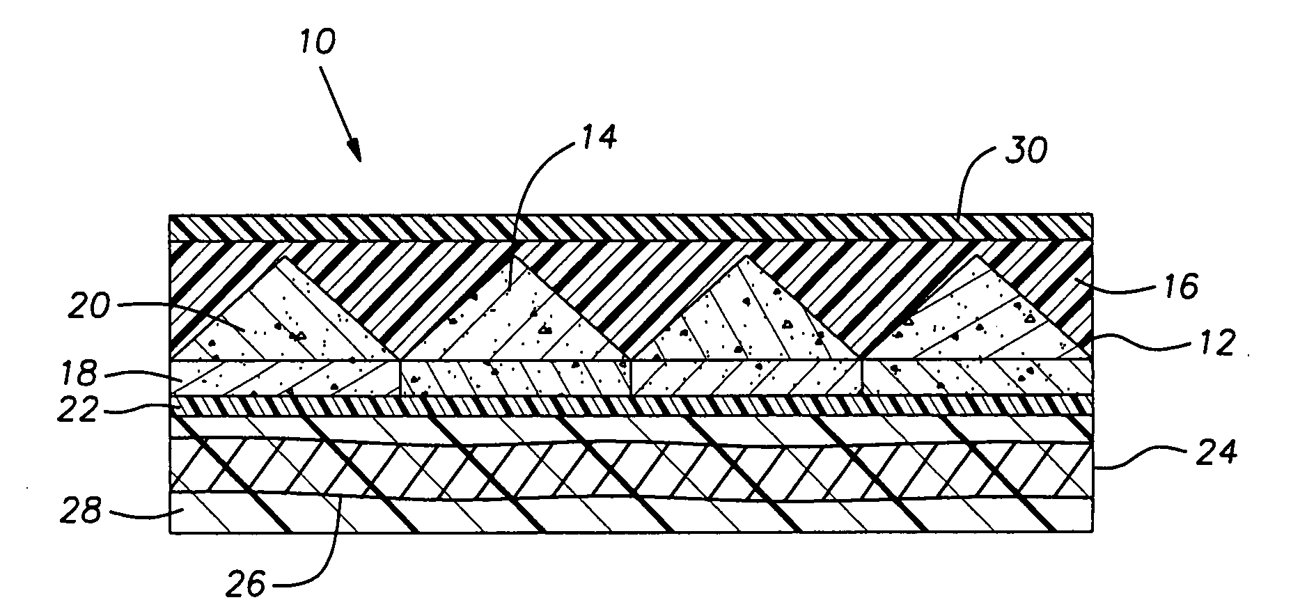
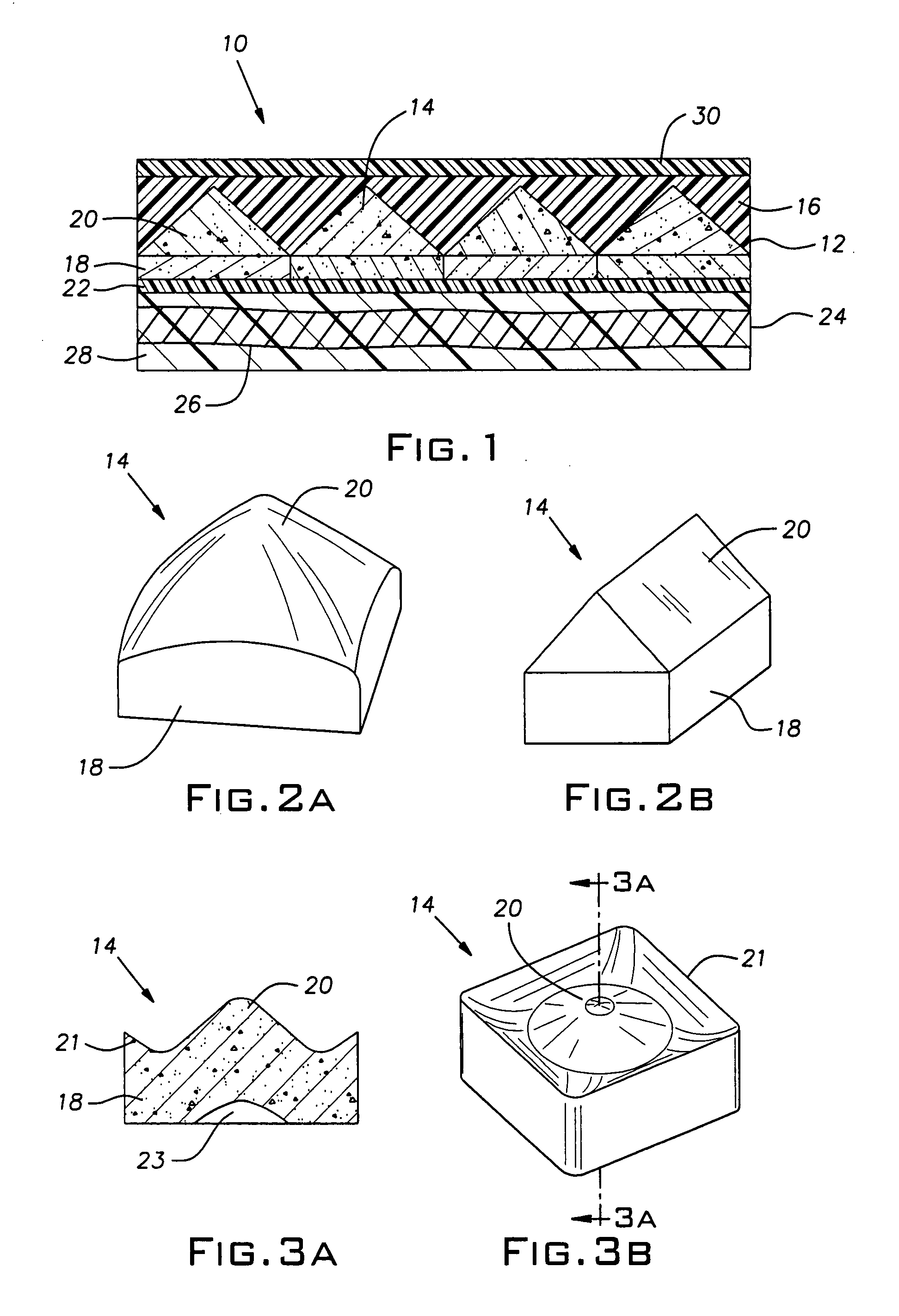
[0100]A cone shaped alumina ceramic tile with a square base having length and width of about 50 mm (cone design CD1) and with a hemi-spherical cavity about 12 mm deep and about 34 mm wide having areal density of 14.14 lbs / ft2 were bonded to a fiberglass composite plate (6×6 inch and 0.5 inch thick, 5.2 lbs / ft2). The sample was mounted in an aluminum picture-frame ha...

example 2

[0101]A ceramic cone shaped alumina tile with a square base (about 50×50 mm) of cone design CD1 having an areal density of 14.6 lb / ft2 was bonded to a High Hard Armor steel plate (HHA) that was 0.15 inch thick. The ceramic tile had a hemispherical cavity with maximum depth of about 13.8 mm and width of about 35 mm. The tile was placed in a 6×6 inch aluminum frame with 4×4 inch opening. The extra space between the target tile and aluminum frame was filled with ¾ inch alumina balls. Test projectile was .50 Cal APIT. The impact location was recorded by using a witness paper before the impact. The hit location was at the mid-point of the cone where ceramic thickness was close to minimum. The velocity measurements showed values of 2684 and 2669 ft / sec. There was no penetration into steel although it showed localized deformation. The total areal density of the armor sample was 20.7 lbs / ft2, a number distinctly less than 50% of the areal density of RHA needed to defeat the equivalent balli...

example 3

[0102]Two flat alumina tiles, 15 and 6 mm thick were bonded to 0.15 inch HHA plate and tested using a procedure described in examples 1 and 2 and the projectile was .50 Cal APIT. The total areal density was 22.6 lbs / ft2. The armor did not stop the projectile. The velocity was about 2730 feet / sec.


PUM

PropertyMeasurementUnit
diameteraaaaaaaaaa
widthaaaaaaaaaa
thicknessaaaaaaaaaa

Abstract

A composite armor including a disrupting layer and a backing layer provides protection against blast and ballistic threats. The disrupting layer includes ceramic particles or tiles that disrupt the incoming projectile, while the backing layer prevents penetration past the armor by the disrupted projectile. The disrupting layer may include a layer of polygonal ceramic tiles with a deflecting front surface, encased by a retaining polymer, and may also include fire-retarding particles.

Description

CONTINUING APPLICATION DATA[0001]This application claims the benefit of U.S. Provisional Application No. 60 / 761,270, filed Jan. 23, 2006, U.S. Provisional Application No. 60 / 761,268, filed Jan. 23, 2006, U.S. Provisional Application No. 60 / 761,269, filed Jan. 23, 2006, and U.S. Provisional Application No. 60 / 849,940, filed Oct. 6, 2006, which are incorporated by reference herein.FIELD OF THE INVENTION[0002]The invention relates to composite armor. More specifically, the invention relates to composite armor including encapsulated ceramic material that may be used to protect vehicles from ballistic and overpressure threats.BACKGROUND OF THE INVENTION[0003]Increased levels of unconventional or asymmetric warfare have led to the need to protect vehicles and / or personnel from munitions typically used in this type of warfare, such as small arms fire and improvised explosive devices (IEDs). While a variety of means are available to minimize casualties from these threats, such as increased ...

Claims


Application Information

Patent Timeline
Patent Type & Authority Applications(United States)
IPC IPC(8): F41H5/02
CPCF41H5/0421F41H5/0492F41H5/0428
Inventor MOORE, III, DAN T.SANE, AJITLENNARTZ, JEFFBUDINGER, BRUCE O.EUCKER, JAMES L.MILLIREN, CHARLES M.
Owner INTPROP HLDG
Why Eureka
Try Eureka