Solar Concentrator

a solar concentrator and array technology, applied in the field of solar concentrators, can solve the problems of the cost of manufacturing itself, and achieve the effect of enhancing the manufacturability of the solar concentrator array and discharging hea

Inactive Publication Date: 2009-05-07
SOLFOCUS
View PDF8 Cites 33 Cited by
  • Summary
  • Abstract
  • Description
  • Claims
  • Application Information

AI Technical Summary

Benefits of technology

[0005]The present invention is a solar concentrator array utilizing a monolithic array of primary mirrors with a metal layer deposited on its backside for electrical purposes and for dissipating heat. In one embodiment, the array of primary mirrors may be formed by glass slumping. The size of the primary mirrors is chosen to accommodate design aspects related to performance, manufacturing processes, cost, and thermal management. An electrical package, which in one embodiment is a molded leadframe, provides the electrical circuitry between a solar cell and the metal layer. The electrical package may be configured with features such as an aperture or side edges to enhance manufacturability of the solar concentrator array. Further optional features of the invention include a non-imaging concentrator and an array of secondary mirrors integrally formed with a front panel of the solar concentrator.

Problems solved by technology

Manufacturing cost itself is affected by other aspects, such as material costs, the number of components required for assembly, manufacturing tolerances, and processing efficiencies.

Method used


Image

  • Solar Concentrator
  • Solar Concentrator
  • Solar Concentrator

Examples


Embodiment Construction

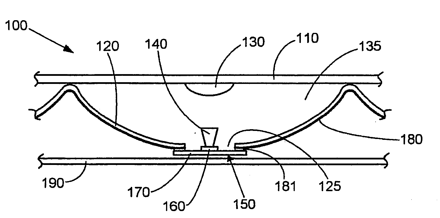
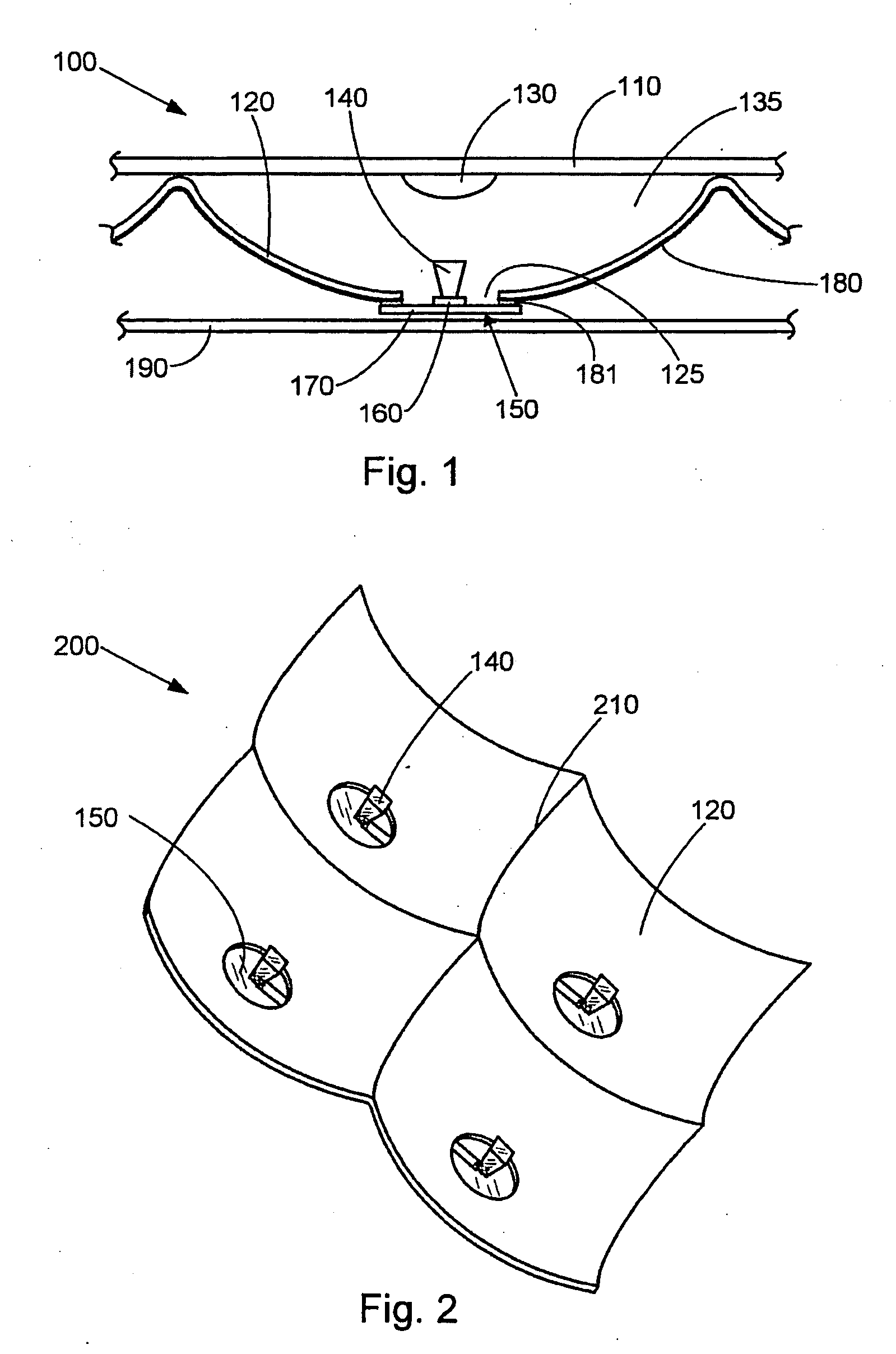
[0021]FIG. 1 depicts a simplified cross-sectional view of an exemplary embodiment of the solar concentrator of the present invention. A solar concentrator unit 100 includes a front panel 110, a primary mirror 120 with a central opening 125, a secondary mirror 130, an optional non-imaging concentrator 140, and a receiver assembly 150 which incorporates a solar cell 160 and an electrical package 170. A metal layer 180 is deposited on the backside of primary mirror 120 for electrical and thermal purposes. An optional backpan 190 may be used to provide support for and protection for an array of solar concentrator units 100, as well as to provide heat dissipation. In the operation of this embodiment, solar radiation enters solar concentrator unit 100 through front panel 110 and reflects off of primary mirror 120 to secondary mirror 130. Secondary mirror 130 then reflects the radiation to non-imaging concentrator 140 which transmits the light to solar cell 160 for conversion to electrical...


PUM

PropertyMeasurementUnit
lengthaaaaaaaaaa
sizeaaaaaaaaaa
electricalaaaaaaaaaa

Abstract

The present invention is an improved solar concentrator array utilizing a monolithic array of primary mirrors with a metal layer deposited on its backside for electrical purposes and for dissipating heat. The array of primary mirrors may be formed by glass slumping. The size of the primary mirrors is chosen to accommodate design aspects related to performance, manufacturing processes, cost, and thermal management. An electrical package, which in one embodiment is a molded leadframe, provides the electrical circuitry between a solar cell and the metal layer. The electrical package may be configured with features such as an aperture or side edges to enhance manufacturability of the solar concentrator array. An array of secondary mirrors may be integrally formed with a front panel of the solar concentrator.

Description

RELATED APPLICATIONS[0001]This application is a continuation-in-part of the following: (1) U.S. patent application Ser. No. 12 / 044,939 filed on Mar. 8, 2008, entitled “Monolithic Glass Array,” which claims priority to U.S. Provisional Patent Application Ser. No. 60 / 985,215 filed on Nov. 3, 2007, entitled “Monolithic Mirror Array”; and (2) U.S. Provisional Patent Application Ser. No. 61 / 016,314 filed on Dec. 21, 2007, entitled “Leadframe Receiver Package for Solar Concentrator,” all of which are hereby incorporated by reference as if set forth in full in this application for all purposes.BACKGROUND OF THE INVENTION[0002]Solar concentrators are solar energy generators which increase the efficiency of converting solar energy into DC electricity. Solar concentrators known in the art utilize, for example, parabolic mirrors and Fresnel lenses for focusing incoming solar energy. Another type of solar concentrator, disclosed in U.S. Patent Publication No. 2006 / 0266408, entitled “Concentrato...

Claims


Application Information

Patent Timeline
Patent Type & Authority Applications(United States)
IPC IPC(8): H01L31/052H01L31/18
CPCY02E10/52Y10T29/49117H01L31/0547
Inventor MILBOURNE, MICHAELCHAN, HING WAHELLSWORTH, JASONBAILEY, DARRELSHOOK, GILLPRATHER, ERIC
Owner SOLFOCUS
Why Eureka
Try Eureka