Ion mobility spectrometer with substance collector

a technology substance collector, which is applied in the direction of instruments, particle separator tube details, separation processes, etc., can solve the problems of dust, external collectors, and dust, and achieve the effect of reducing the sensitivity of ion mobility spectrometer, reducing desorption temperature and time, and preventing low volatility into the collector

Active Publication Date: 2009-05-07
BRUKER OPTICS GMBH & CO KG
View PDF61 Cites 25 Cited by
  • Summary
  • Abstract
  • Description
  • Claims
  • Application Information

AI Technical Summary

Benefits of technology

[0010]During a collecting phase, circulating gas, for example containing the analyte substances to be measured, is transferred from the membrane inlet into the substance collector, before passing through a pumping device and a filter, so that the analyte substances are accumulated in the substance collector. During the desorption and injection phases, the stored substances are released and transferred into the measuring tube of the ion mobility spectrometer, where they are analyzed. The analyte substances collected by the substance collector are enriched by releasing them as short substance pulses. The substance collector may be shock heated to achieve the fastest possible release (i.e., desorption) of the substances in order to generate highly concentrated, short-duration analyte substance pulses. Actively cooling the substance collector during the collecting phase may improve the storage of analyte substances in the substance collector.
[0011]A high enrichment factor may be achieved by locating the substance collector within the internal gas circuit, avoiding any temporal broadening of the released analyte substance pulse, as occurs on passage through a membrane. The internal substance collector may be located in close proximity to the measuring tube of the ion mobility spectrometer. As a result, the detection power of an ion mobility spectrometer is significantly increased. Moreover, an internal substance collector may be more compact than an external substance collector.
[0012]Locating the substance collector within the internal gas circuit protects it from dust, whereas an external collector, when exposed to heavy dust, can quickly become blocked and require replacement.
[0014]In contrast to substance collectors that collect analyte substances outside the gas circuit and then are themselves incorporated into the internal gas circuit, in some examples, only analyte substances that can penetrate through the inlet membrane are collected. This has the advantage that the ingress of water vapor and substances of very low volatility into the collector is largely prevented. An increased concentration of water vapor may lower the sensitivity of the ion mobility spectrometer. Analyte substances of relatively low volatility may be released again at relatively high temperatures. Separating them out permits lower desorption temperatures and times, thus, for example, significantly saving energy (essential for mobile instruments) and reducing the aging of the collecting material.

Problems solved by technology

Locating the substance collector within the internal gas circuit protects it from dust, whereas an external collector, when exposed to heavy dust, can quickly become blocked and require replacement.

Method used


Image

  • Ion mobility spectrometer with substance collector
  • Ion mobility spectrometer with substance collector
  • Ion mobility spectrometer with substance collector

Examples


Embodiment Construction

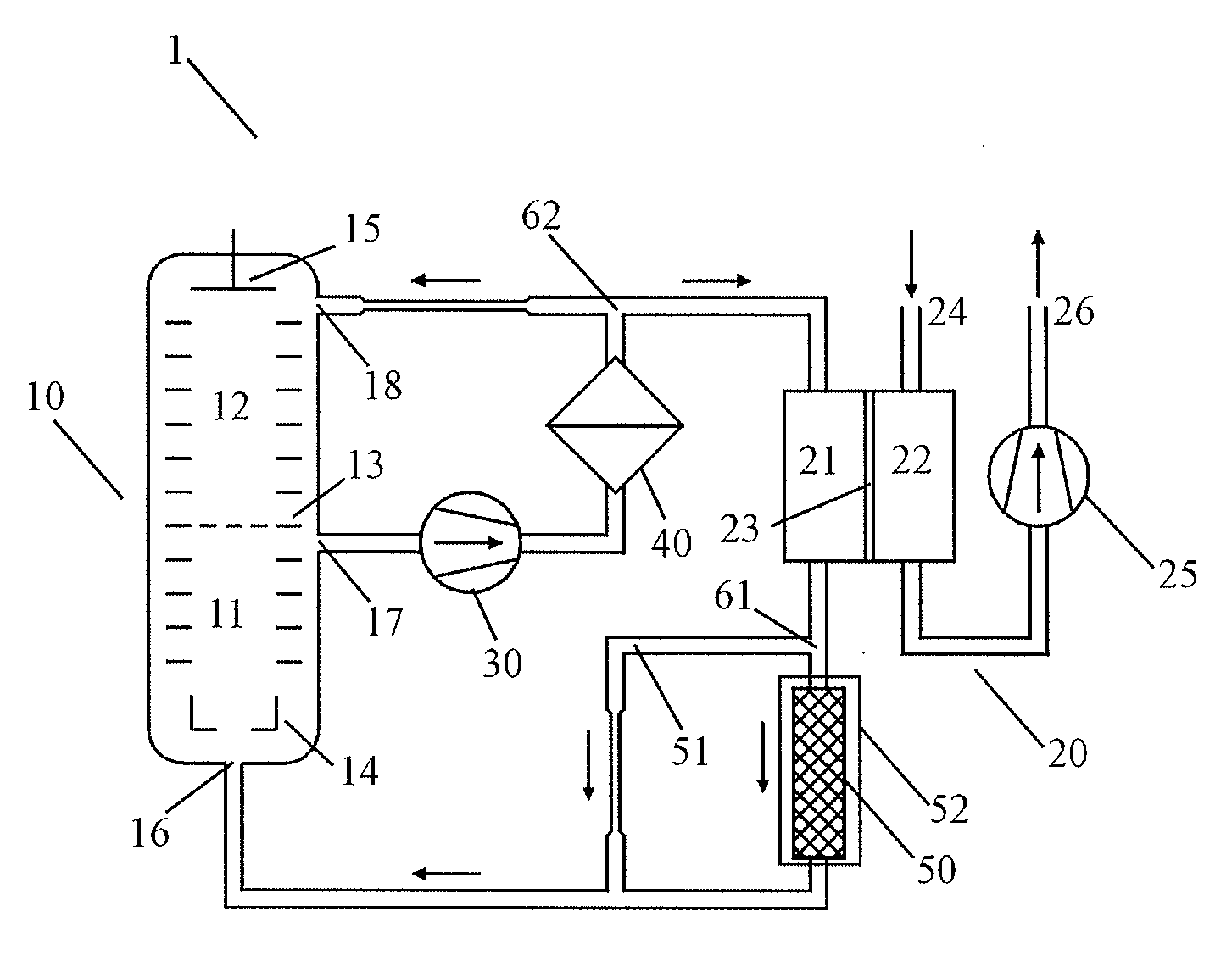
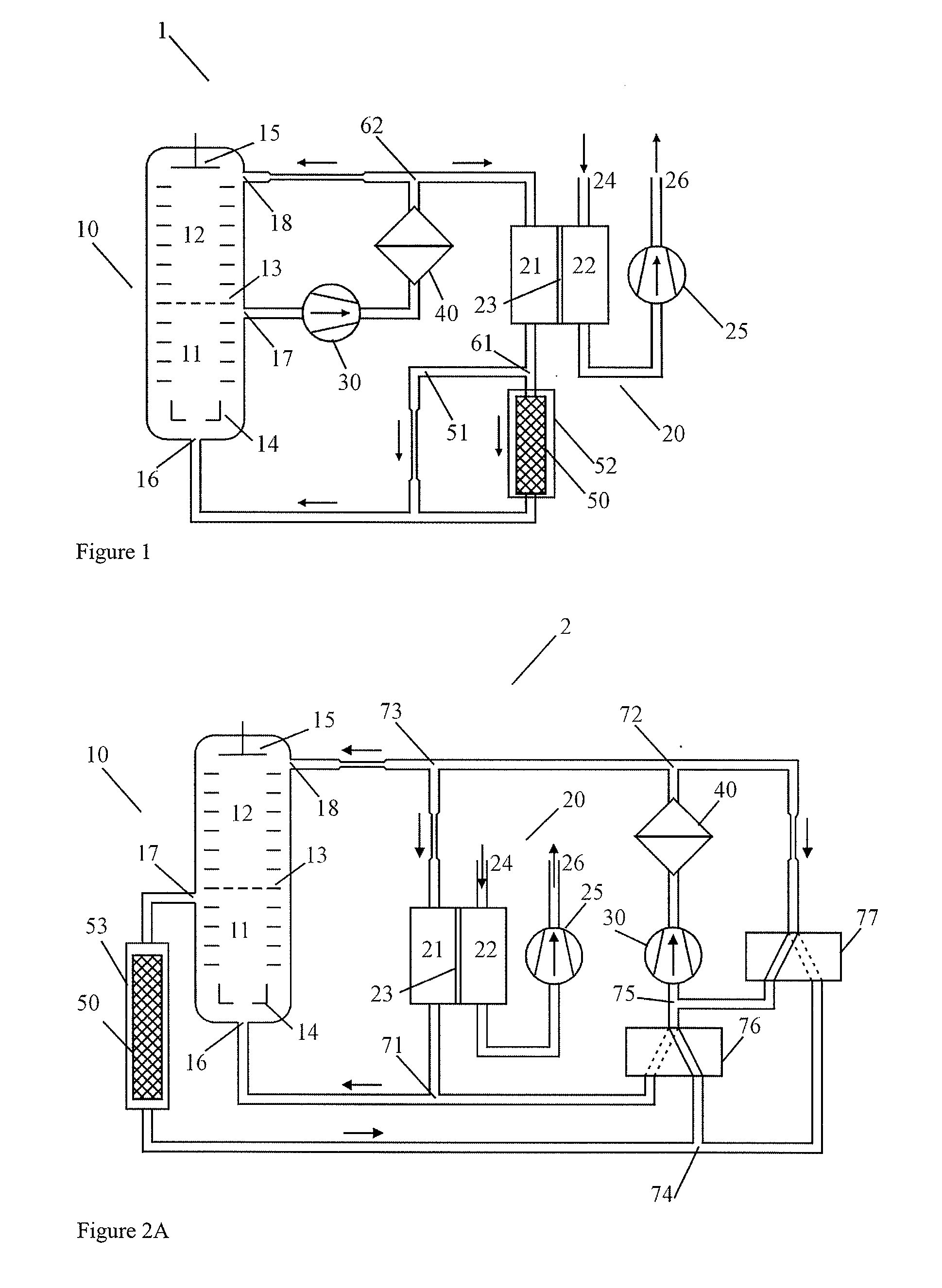
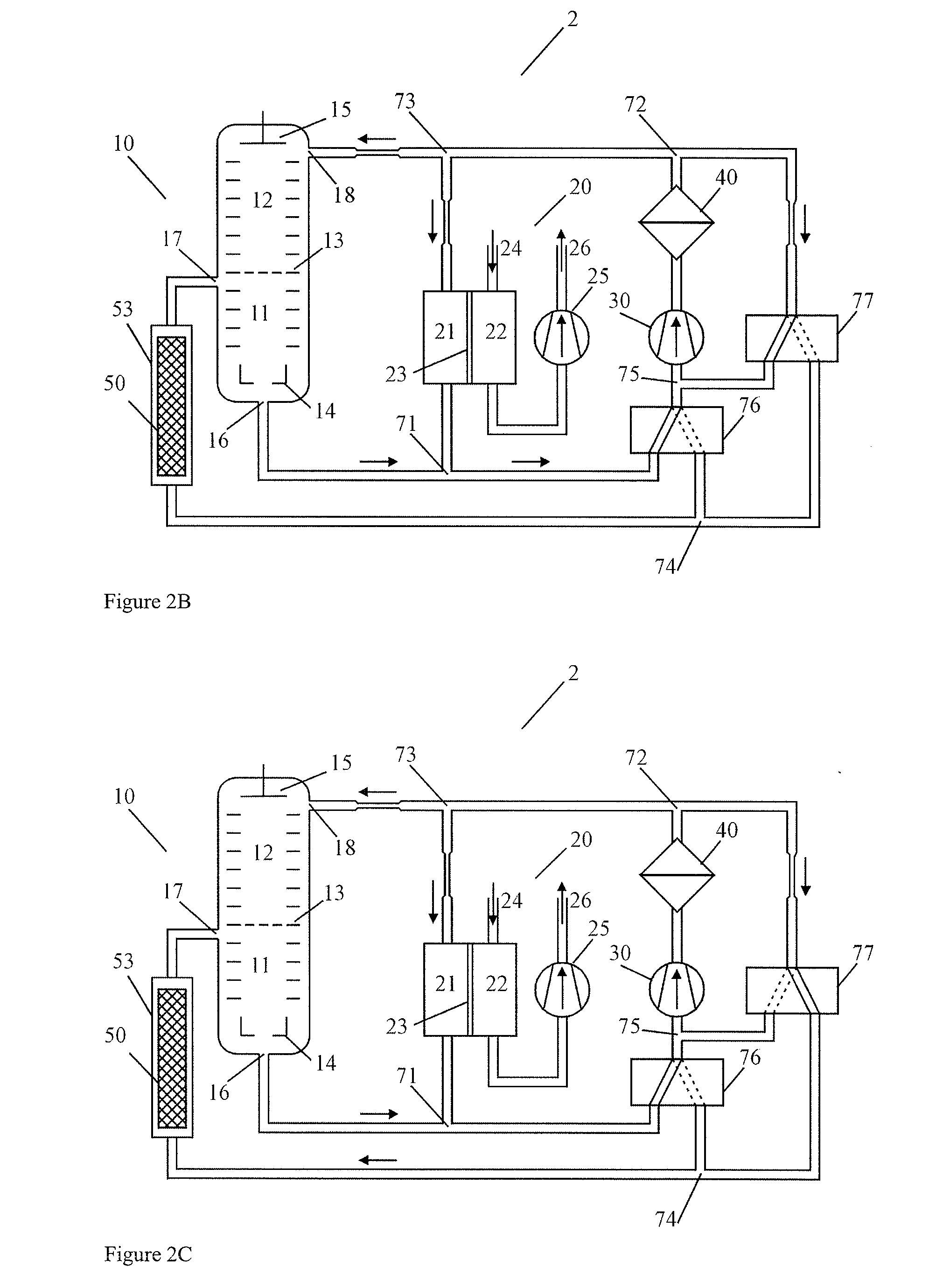
[0022]FIG. 1 illustrates a first example of an ion mobility spectrometer 1. The ion mobility spectrometer comprises an internal substance collector 50 and a measuring tube 10, for example a drift time measuring tube. Drift time ion mobility spectrometers are the most widely used ion mobility spectrometers. Therefore, this disclosure primarily contemplates the drift time ion mobility spectrometers. However, other types of ion mobility spectrometers, for example the “Aspiration Ion Mobility Spectrometer” from the Finnish company Environics Oy and the “Asymmetric Field Ion Mobility Spectrometer” (FAIMS), should not be regarded as excluded from the following disclosure.

[0023]The measuring tube 10, includes a grating grid 13 that separates a reaction chamber 11 and a drift chamber 12. Generally, gas molecules are ionized in the reaction chamber 11 and relatively close to a radiation source 14. In one example, the radiation source 14 comprises a beta emitter such as 63Nickel. Analyte subs...


PUM

PropertyMeasurementUnit
humidityaaaaaaaaaa
humidityaaaaaaaaaa
ion mobility spectrometeraaaaaaaaaa

Abstract

A method for operating an ion mobility spectrometer that comprises a measuring tube, a substance collector and a membrane inlet, the measuring tube, the substance collector and the membrane inlet defining a closed internal gas circuit, comprising separating the closed internal gas circuit from an external sample gas flow through the membrane inlet, transferring circulating gas containing an analyte substance from the membrane inlet to the substance collector, the analyte substance accumulated in the substance collector, releasing the accumulated analyte substances, and transferring the released analyte substances to the measuring tube.

Description

PRIORITY INFORMATION[0001]This patent application claims priority from German patent application 10 2007 052 801.0 filed Nov. 6, 2007, which is hereby incorporated by reference.FIELD OF THE INVENTION[0002]The disclosure relates generally to an ion mobility spectrometer, and in particular to an ion mobility spectrometer with a closed internal gas circuit.BACKGROUND OF THE INVENTION[0003]Gaseous substances are analyzed and continuously monitored in a large number of applications, such as environmental analysis, control of chemical processes, monitoring of production facilities, and in both civil and military fields for the detection of chemical warfare agents (CWAs) or explosives. Ion mobility spectrometry is a method introduced in the 1970s for high-sensitivity detection of potentially dangerous analyte substances in ambient air or other sample gases.[0004]An ion mobility spectrometer (IMS) can be operated at ambient pressure. Ion mobility spectrometers are relatively compact and can...

Claims


Application Information

Patent Timeline
Patent Type & Authority Applications(United States)
IPC IPC(8): H01J49/02B01D59/44
CPCH01J49/0427G01N27/622G01N1/22G01N1/4005H01J49/40
Inventor LANDGRAF, JURGEN
Owner BRUKER OPTICS GMBH & CO KG
Why Eureka
Try Eureka