Outer rotor motor

a rotor motor and outer rotor technology, applied in the direction of sliding contact bearings, machines/engines, rigid support of bearings, etc., can solve the problems of low yield, component cost and/or machining cost, thickness of material, etc., to increase dimensional tolerances, high concentricity, and accurate assembly

Active Publication Date: 2009-05-07
SHINANO KENSHI
View PDF13 Cites 10 Cited by
  • Summary
  • Abstract
  • Description
  • Claims
  • Application Information

AI Technical Summary

Benefits of technology

[0011]The present invention was conceived to solve the problems described above and it is an object of the present invention to provide an outer rotor motor that uses a thin material and has a lower machining cost due to the use of press molding, that can be used even when there is a large difference between the stator inner diameter and the bearing outer diameter, and is relatively unaffected by the dimensional accuracy with which components are attached to the inside and outside of the housing, resulting in high durability.
[0015]By using the outer rotor motor described above, the bearing housing has a housing main body that is formed in a cylindrical shape by plastic deformation caused by press molding a metal matrix and the bearing is attached to an inner circumferential surface of the housing main body. At least one protruding surface is formed on the bearing housing by plastic deformation so as to protrude further outward than the housing main body, and the stator core is attached to an outer circumference side of the at least one protruding surface. In this way, by molding the bearing housing in a shape that includes at least one protruding surface, it is possible to adjust the projecting amount by press molding even in a motor where there is a large difference between the stator inner diameter and the bearing outer diameter. Also, by providing the at least one protruding surface that protrudes further outward than the housing main body by press molding, it is possible for the elasticity of the curved portions to absorb stress during press fitting, which increases dimensional tolerances. Here, by combining the bearing housing which is press molded and a casing which is molded from resin, since the stator core and the bearing are pressed onto and attached to the inner and outer circumferential surfaces of the bearing housing, it is possible to provide an outer rotor motor that has high concentricity, can be accurately assembled, and has high durability.
[0016]Since the bearing housing may include the housing main body, which has been produced by drawing a metal sheet into a cylinder using a press mold or by molding a metal cylinder using a press mold, and the at least one protruding surface, which is molded by plastic deformation using a press mold so as to protrude further outward than the housing main body, it is possible to form the bearing housing with little dimensional fluctuations and with a low machining cost.
[0017]Also, if a core supporting portion, which includes a front end that is inserted into a gap between the housing main body and the stator core and a stepped portion that supports the stator core, is integrally molded with the casing from resin, by using a core supporting portion that is integrally molded in an arbitrary shape together with the casing, it is possible to position the stator core while filling a gap between the housing and the stator core that is formed outside the housing, which makes it easier to assemble the motor components and improves the assembled accuracy. It is also possible to fix the housing main body and the casing by partially crimping, for example, an end part of the housing in a state where the stator core has been fitted onto the housing.

Problems solved by technology

However, when the housing is made by cutting, there are the problems of wasted material (which lowers the yield) and a component cost and / or machining cost being incurred when connecting the housing to the motor base.
Also, when the housing is formed from carrying out burring on a metal base material or is drawn into a simple cylindrical shape, changes in thickness that accompany press molding and limitations on the thickness of the material make it difficult to set the dimensions of the stator inner diameter and the bearing outer diameter.
Such housing cannot be used in motors where there is a large difference between the stator inner diameter and the bearing outer diameter.
When the housing and the casing are both integrally molded from resin, the force with which components are attached to the inner and outer circumferences of the housing is susceptible to variation due to changes in temperature (i.e., due to thermal expansion), and there is poor durability due to abrasion and deformation.

Method used


Image

  • Outer rotor motor
  • Outer rotor motor
  • Outer rotor motor

Examples


Embodiment Construction

[0021]Preferred embodiments of an outer rotor motor according to the present invention will now be described with reference to the attached drawings. In these embodiments, an outer rotor-type DC brushless motor will be described as one example.

[0022]The overall construction of a DC brushless motor will now be described with reference to FIG. 1.

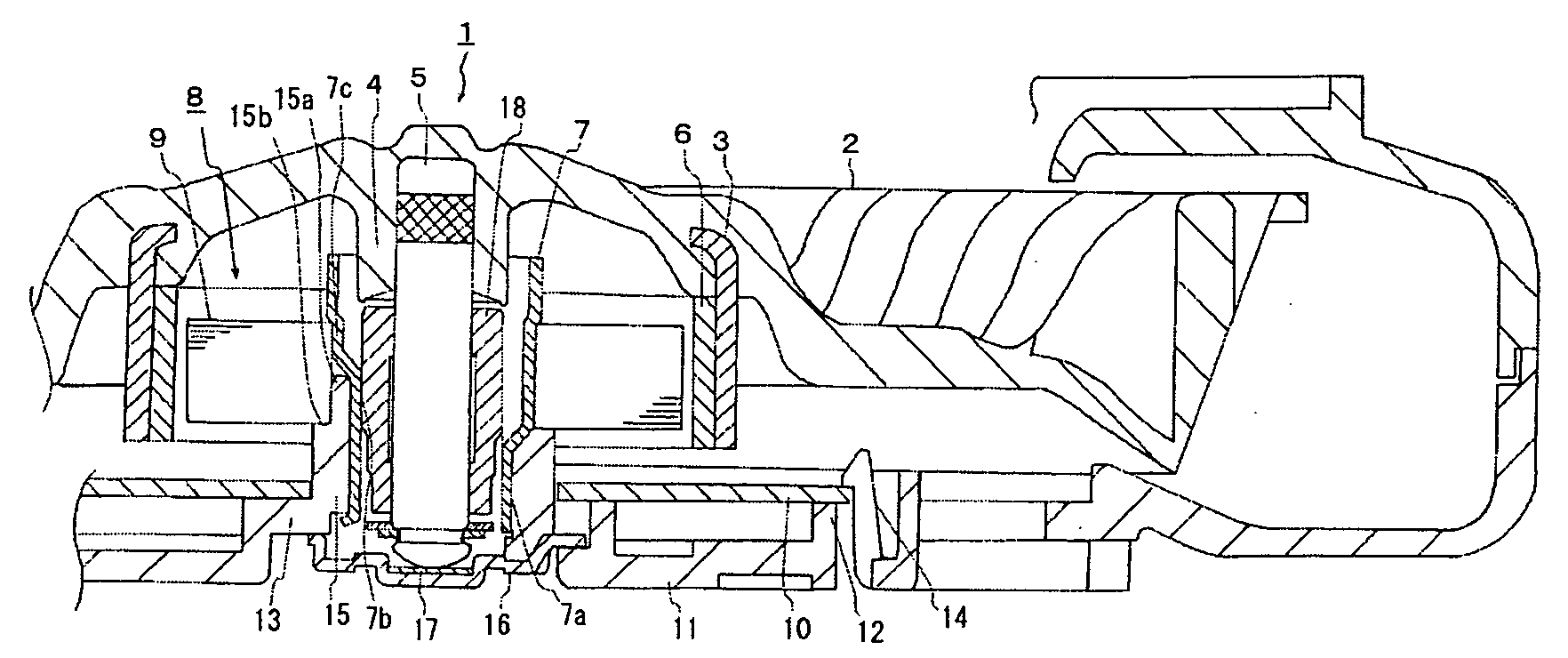
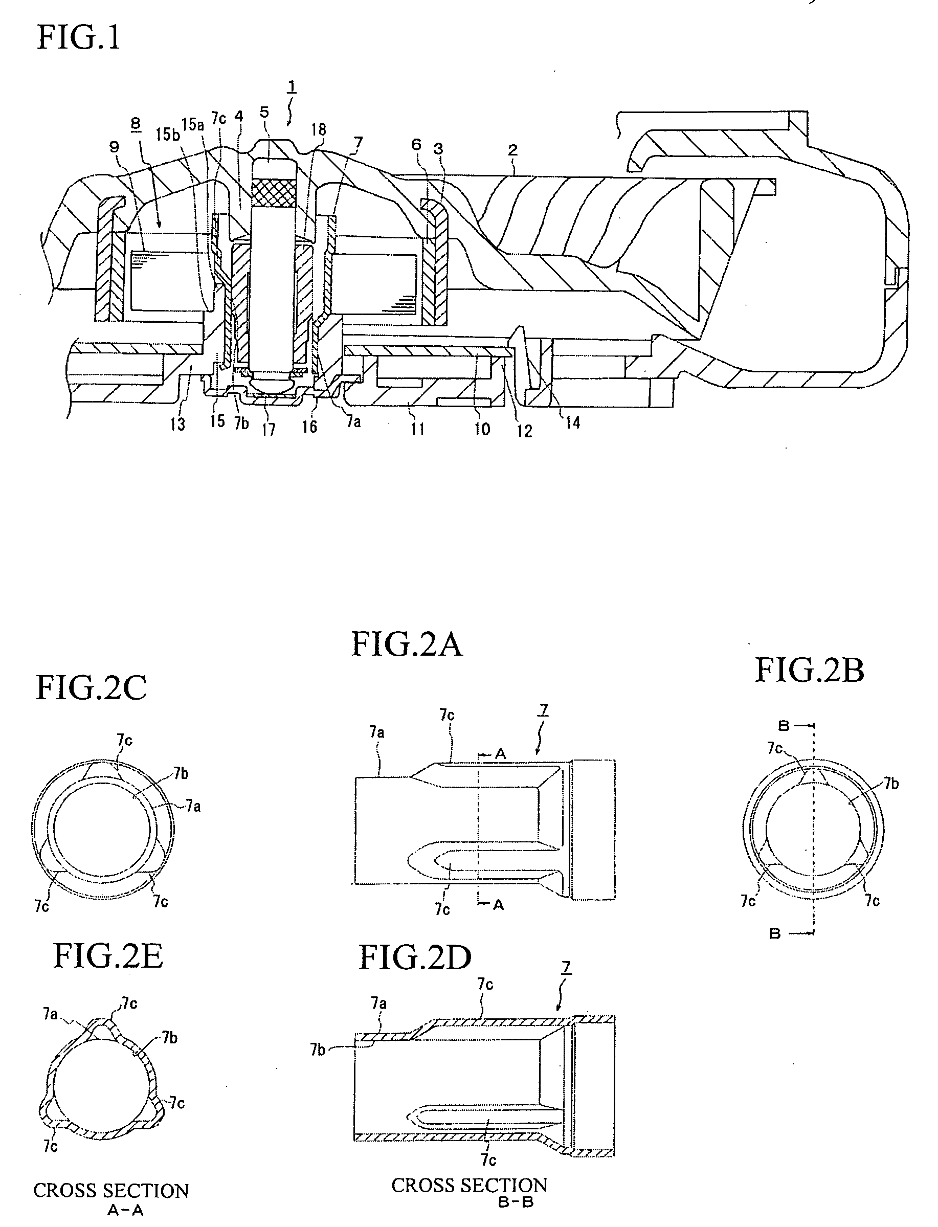
[0023]In FIG. 1, an integral construction where an impeller 2 has been insert-molded with a cylindrical rotor yoke 3 is used as a rotor 1. A motor shaft 5 is integrally fixed to a hub 4 of the impeller 2. A ring-shaped magnet 6 is fixed to an inner circumferential surface of the rotor yoke 3. The magnet 6 is magnetized so that north poles and south poles are alternately formed in the circumferential direction. The motor shaft 5 is rotatably supported by a bearing 18 that is press fitted into a bearing housing 7 provided on the stator.

[0024]The stator 8 has a stator core 9 fitted onto an outer circumference side of the bearing housing 7 which i...


PUM


Abstract

An outer rotor motor has a bearing housing with reduced machining and material costs, can be assembled with high accuracy, and has favorable durability. A bearing is attached to an inner circumferential surface of a housing main body that has been formed in a cylindrical shape by plastic deformation caused by press molding a metal matrix. At least one protruding surface is formed by plastic deformation so as to protrude further outward than the housing main body, and the stator core is attached to the outer circumference-side of the at least one protruding surface.

Description

BACKGROUND OF THE INVENTION[0001]1. Field of the Invention[0002]The present invention relates to an outer rotor motor used for example in an OA appliance such as a printer, a copier, or a DVD drive, an in-vehicle appliance such as a seat cooler or a cooling fan, or a projector.[0003]2. Related Art[0004]One example of an outer rotor-type DC brushless motor will now be described. A housing in the form of a hollow cylinder is attached to a motor base, a bearing is attached to the inner circumference side of the housing, and a motor substrate and a stator core are attached to the outer circumference side of the housing. A rotor including a magnet is rotatably attached via the bearing with a rotor shaft of the rotor inserted inside the housing.[0005]The housing is produced by machining from a metal matrix or cutting a material that has been molded in advance by die-cast molding for example, and is fixed to the motor base by screws or the like. Alternatively, the housing may be drawn into...

Claims


Application Information

Patent Timeline
Patent Type & Authority Applications(United States)
IPC IPC(8): H02K5/16
CPCF04D17/16F16C17/04F16C35/02F04D25/0646H02K5/1675H02K7/14F04D25/062H02K1/2786H02K1/2791
Inventor KODAMA, YUJI
Owner SHINANO KENSHI
Why Eureka
Try Eureka