Temperature compensation of collector-voltage control RF amplifiers

a technology of voltage control and amplifier, applied in the field of amplifier compensation, can solve the problems of high undesirable and inconvenient transmission of signals outside of the frequency band and power level assigned, violation of communication standards and associated governmental regulations, and inability to receive and decode signals that do not comply with the standard or desired transmit parameters

Active Publication Date: 2009-05-07
SKYWORKS SOLUTIONS INC
View PDF85 Cites 56 Cited by
  • Summary
  • Abstract
  • Description
  • Claims
  • Application Information

AI Technical Summary

Benefits of technology

[0016]Also disclosed herein is a system for temperature compensating an amplifier. In one configuration, this embodiment comprises a first input configured to receive a band gap current signal and a second input configured to receive a temperature proportional current signal. A network is provided and configured to combine the band gap current signal and the temperature proportional current signal to create an offset signal. Likewise, a differing amplifier is prov...

Problems solved by technology

Signals transmitted outside of this assigned frequency band and power level are highly undesirable and in violation of the standard and possibly one or more governmental regulations.
Moreover, signals that do not comply with the standard or desired transmit parameters may not be possible of reception and decoding at a receiving station
Undesirable variation in the RF envelope control may result in performance degradation, resulting in violation of the communication standard and associated governmental regulations.
In particular, in an electronic device, variation in temperature may result in variation in device and circuit operation.
For example, in a GaAs die in a power amplifier (PA) module, the temperature variation causes variation in RF envelope control, resulting in degradation of the adjacent channel spectrum.
However, in higher precision sy...

Method used


Image

  • Temperature compensation of collector-voltage control RF amplifiers
  • Temperature compensation of collector-voltage control RF amplifiers
  • Temperature compensation of collector-voltage control RF amplifiers

Examples


Embodiment Construction

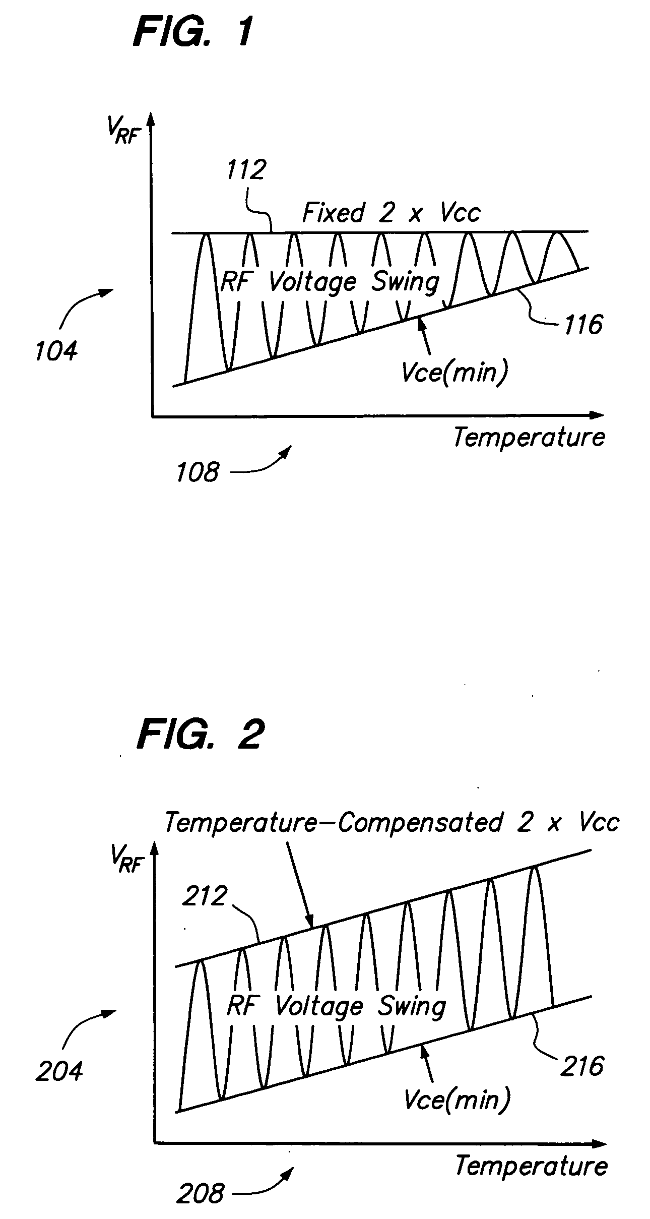
[0028]To overcome the drawbacks of the prior art, a temperature compensated amplifier is disclosed. In the temperature compensated system described herein the voltage Vce(sat) remains fixed, although dependent on temperature, while the voltage Vcc is compensated. FIG. 2 illustrates an example plot of such an arrangement. As shown in FIG. 2, a vertical axis 204 represents RF voltage while a horizontal axis 208 represents temperature. A (2×Vcc) plot 212 is shown as representing the upper range of the RF voltage swing while a Vce(sat) plot 216 represents the lower boundary of the RF voltage swing. In this plot of FIG. 2, as compared to FIG. 1, it can be seen that (2×Vcc) plot 212 has been compensated for temperature such that as temperature increases, so to does Vcc. In this manner, the output power or voltage swing, if so desired, may be maintained constant and not be limited by the upper boundary of (2×Vcc).

[0029]Before discussing the details of the various embodiments of the inventi...


PUM


Abstract

A temperature compensation system for compensating a collector-voltage controlled RF amplifier. To overcome variation that occurs with temperature which can result in signal degradation of the adjacent channel spectrum, a temperature compensated current is utilized to create an offset signal. The offset signal is processed in connection with a control or data signal to generate a temperature compensated voltage source control signal. A differential amplifier may process the data or control signal and the offset signal. The compensated voltage control signal tracks temperature to adapt the applied collector voltage to temperature. This in turn forces the applied collector voltage to vary in response to temperature changes thereby maintaining a constant output power or RF swing. One example environment of use is in an EDGE type GSM system.

Description

1. FIELD OF THE INVENTION[0001]The invention relates to amplifier compensation and in particular to a temperature compensated amplifier and modulation scheme.2. RELATED ART[0002]Communication devices have become popular in the United States and throughout the world. For various reasons, numerous different communication standards have been adopted and implemented in not only the United States, but also, in different countries. Associated with a communication standard is a usually a requirement that the wireless communication device transmit within a particular frequency range, or at a particular power level. Signals transmitted outside of this assigned frequency band and power level are highly undesirable and in violation of the standard and possibly one or more governmental regulations. Moreover, signals that do not comply with the standard or desired transmit parameters may not be possible of reception and decoding at a receiving station[0003]For example, an open-loop polar modulat...

Claims


Application Information

Patent Timeline
IPC IPC(8): H03F1/30
CPCH03F1/30H03F1/32H03F3/19H03F3/245H03F2200/78H03F2200/15H03F2200/447H03F2200/451H03F2200/504H03F2200/108H03F1/302
Inventor RIPLEY, DAVID S.PHILLIPS, KERRY BRENT
Owner SKYWORKS SOLUTIONS INC
Why Eureka
Try Eureka