Flat Panel Display

a flat panel display and display panel technology, applied in the field of flat panel displays, can solve the problems of increasing heating value, reducing the channel for radiating heat, and insufficient merely radiating heat with a fan at present, so as to reduce the number and the length of cable wirings, increase the available space, and secure the effect of heat radiation channels

Inactive Publication Date: 2009-05-07
MAXELL HLDG LTD
View PDF10 Cites 68 Cited by
  • Summary
  • Abstract
  • Description
  • Claims
  • Application Information

AI Technical Summary

Benefits of technology

[0017]As a second advantage of the present invention, the signal processing circuit and other substrates are incorporated into the same substrate, so that cable wirings between the substrates are shortened or laid on the substrate, which decreases the number and the length of cable wirings. This increases available space to easily secure channels for heat radiation. In addition, electromagnetic induction can be less generated to allow reduction in consumption power and improvement in functions of the display device.

Problems solved by technology

However, driving the fan raises heating value, and at the same time, increasing the flat panel display in size also increases heating value and thinning the display decreases a channel for radiating heat.
Merely radiating heat with a fan is insufficient at present.
A magnetic field generated by current flowing temporally varies current itself and increases a current value to require a driving circuit with a larger driving force, further increasing consumption current.

Method used


Image

  • Flat Panel Display
  • Flat Panel Display
  • Flat Panel Display

Examples


Embodiment Construction

[0028]The embodiment of the present invention is described below with reference to the accompanied drawings. In each drawing, composing elements having common functions are given the same reference numerals and duplicate descriptions thereof are omitted.

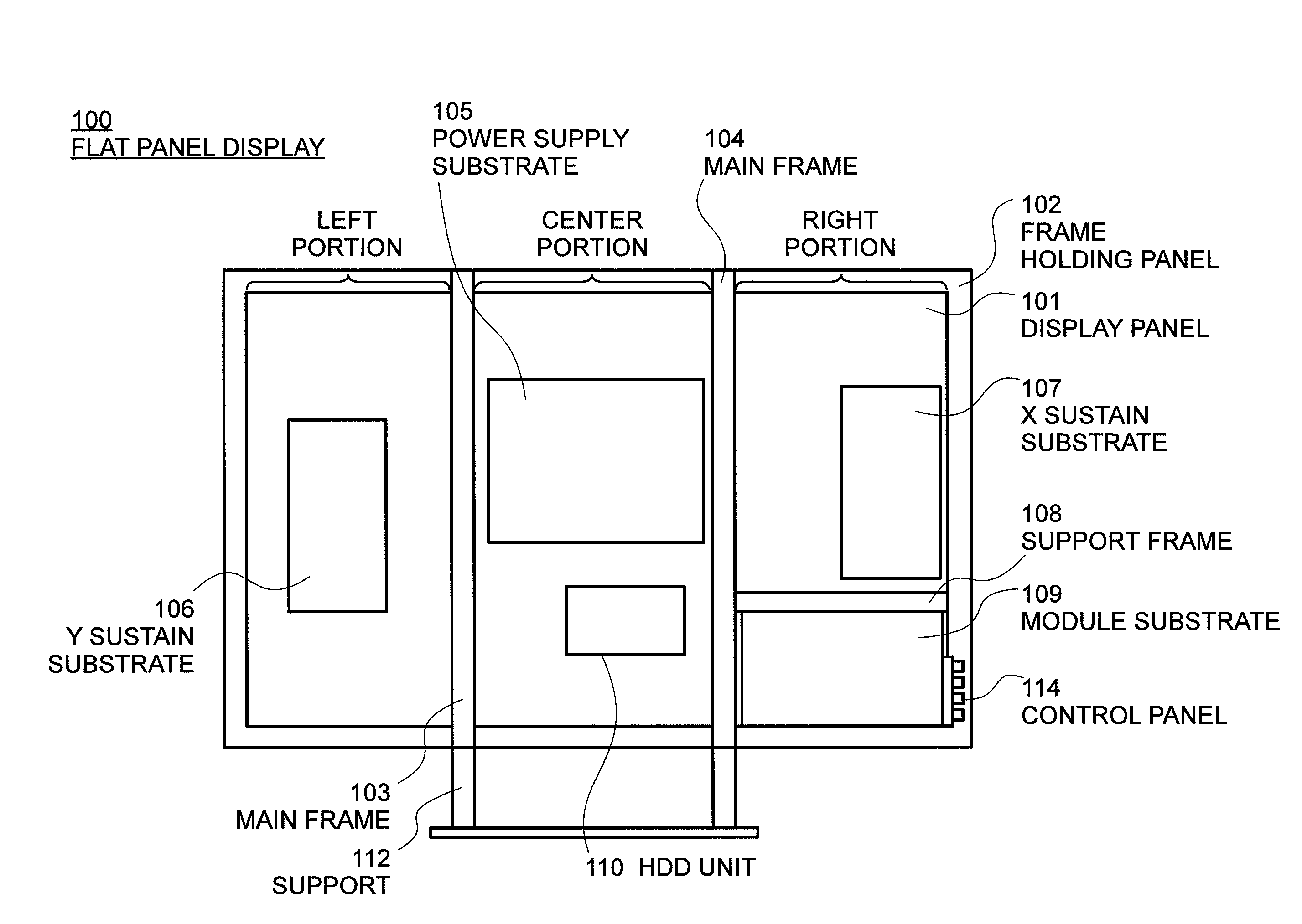
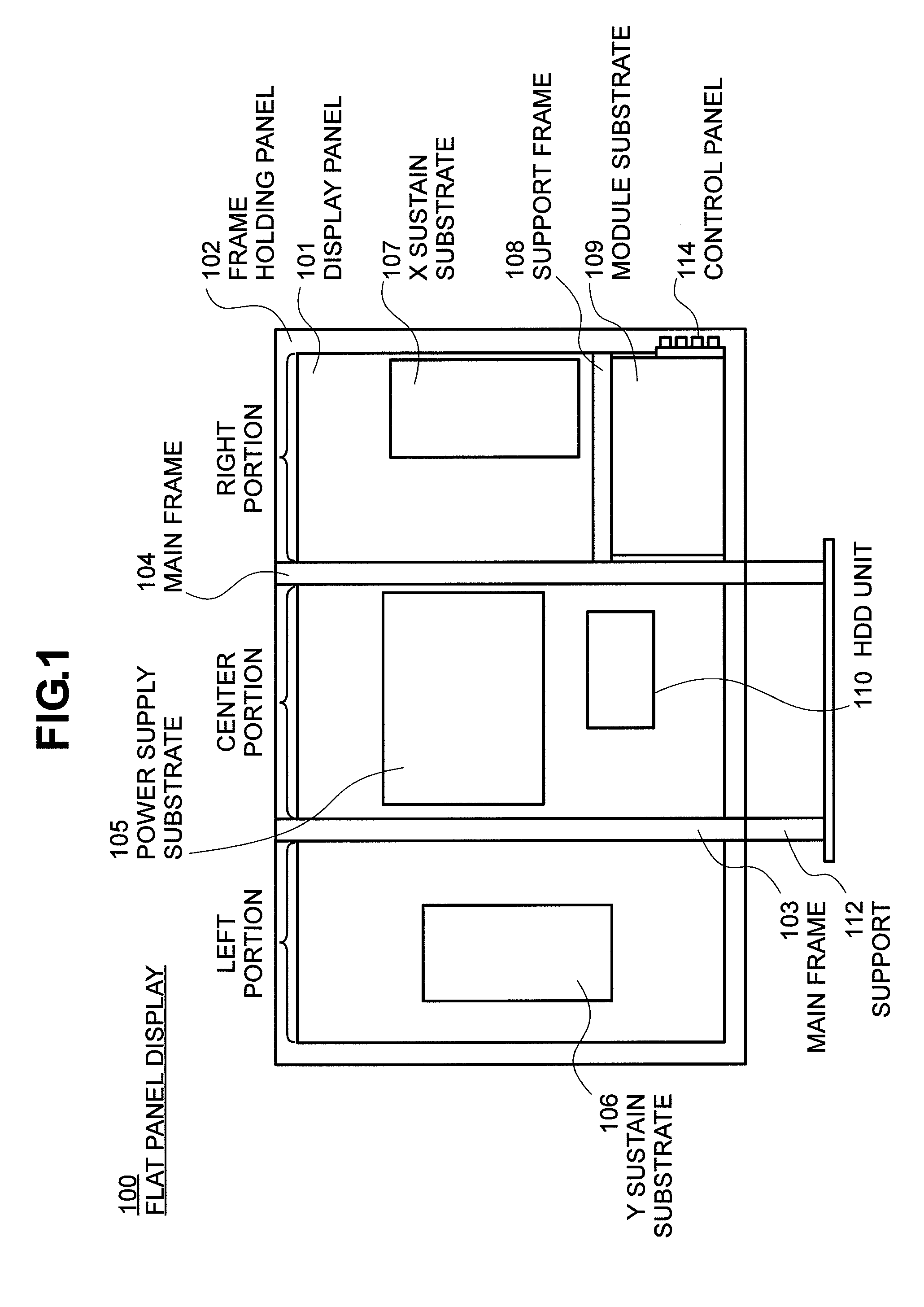
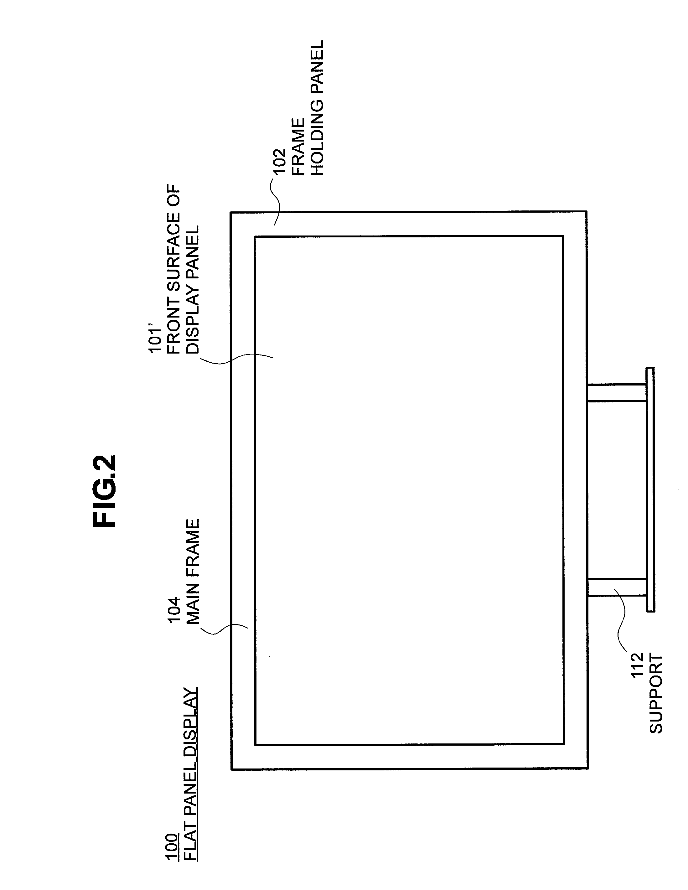
[0029]FIGS. 1 to 6 are diagrams illustrating the configuration of a flat panel display with the PDP as a display device. FIGS. 4 to 6 are diagrams illustrating a configuration inferior in heat radiation. FIGS. 1 to 3 are diagrams illustrating an arrangement in which heat radiation is improved.

[0030]FIG. 4 is a rear view of the flat panel display with its cover removed. FIG. 5 is a front view of the flat panel display illustrated in FIG. 4. FIG. 6 is a schematic cross section viewed from the side of the flat panel display illustrated in FIG. 4. Reference numeral 400 denotes a flat panel display; reference numeral 101 denotes a display panel such as a PDP display device; reference numeral 102 denotes a frame holding the panel; and refe...


PUM


Abstract

Space is decreased in the direction of thickness on a side of a substrates mounted on a back of a flat panel display to adapt requirement for increasing and thinning its size, and most flat panel displays forcibly radiate heat with a fan provided thereon. The present invention provides a flat panel display having fewer heat radiating fans to secure a channel for causing a heat radiating air to flow. Portions where electronic circuit device on a back of a display panel are mounted are divided into three: left; center; and right portions; with a main frame as a border, the electronic circuit device are constructed of four module substrates, the substrate which is the greatest in heating value in the four module substrates (hereinafter referred to as a substrate) is arranged in the center portion and the substrates which are the smallest and the second smallest in heating value therein are arranged in the same portion.

Description

BACKGROUND OF THE INVENTION[0001](1) Field of the Invention[0002]The present invention relates to a flat panel display using a display device such as a plasma display panel, and in particular, to a technique for improving heat radiation.[0003](2) Description of the Related Art[0004]A conventional flat panel display using a display device such as a plasma display panel (PDP) generally displays an image on the front side of the display device (hereinafter referred to as a “display panel”) and mounts a large number of electronic mechanical components on the rear side thereof. For this reason, a user who watches an image views the screen of the panel from the front side thereof.[0005]The flat panel display using the PDP arranges a power supply substrate, a Y sustaining substrate, an X sustaining substrate, a signal processing circuit, an operation substrate and an external input and output substrate on a face opposite to the screen of the panel, i.e., on the rear side thereof and each c...

Claims


Application Information

Patent Timeline
Patent Type & Authority Applications(United States)
IPC IPC(8): H04N5/64H05K7/20
CPCH05K7/20972H04N5/645
Inventor TANAKA, TEPPEINAITO, YASUSHITOMITA, YASUHIROYAMASHITA, YOSHIHARUYAMADA, YUTAKAMIYOSHI, KOHEISEKIGUCHI, SEIICHI
Owner MAXELL HLDG LTD
Why Eureka
Try Eureka