Magnetic head slider manufacturing method

a manufacturing method and slider technology, applied in the direction of manufacturing tools, maintaining head carrier alignment, instruments, etc., can solve the problems of unstable recording magnetization, difficult to have higher density, and magnet poles repel each other, and achieve high precision. high

Active Publication Date: 2009-05-07
SAE MAGNETICS (HK) LTD
View PDF3 Cites 3 Cited by
  • Summary
  • Abstract
  • Description
  • Claims
  • Application Information

AI Technical Summary

Benefits of technology

[0035]With the bar block and the magnetic head slider manufacturing device in the above-described structures, it is also possible to achieve the above-described object of the present invention, which is to adjust the recording element and the reproducing element with high precision and to manufacture the high-quality magnetic head sliders, as in the case of the magnetic head slider manufacturing method.
[0036]The present invention is structured and functions as described above. With the present invention, the reproducing-element polish amount detecting sensor and the recording-element polish amount detecting sensor are formed on the same layer of...

Problems solved by technology

With the longitudinal recording method, however, magnetic poles repel each other.
Thus, it is difficult to have higher density.
Even if it becomes possible to achieve higher density by suppressing repelling of the magnetic poles through thinning films of a recording medium, it is unavoidable to have an issue of heat disturbance with which the recording magnetization becomes unstable because of the heat energy of a room temperature.
However, if the height is too short, fringing fields are generated.
However, with the conventional longitudinal recording method, accuracy in the height of the magnetic pole of the recording element has not been sought so severely.
However, this method has such an issue that both elements cannot be adjusted with high precision since variations in the record...

Method used


Image

  • Magnetic head slider manufacturing method
  • Magnetic head slider manufacturing method
  • Magnetic head slider manufacturing method

Examples


first embodiment

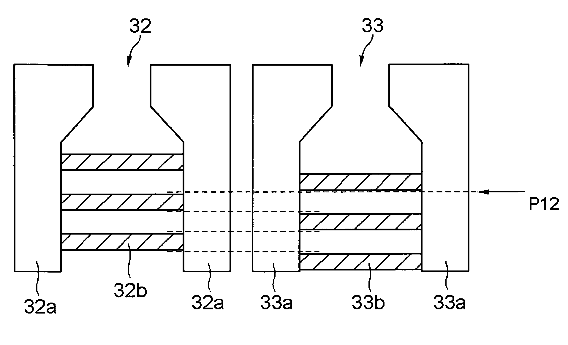
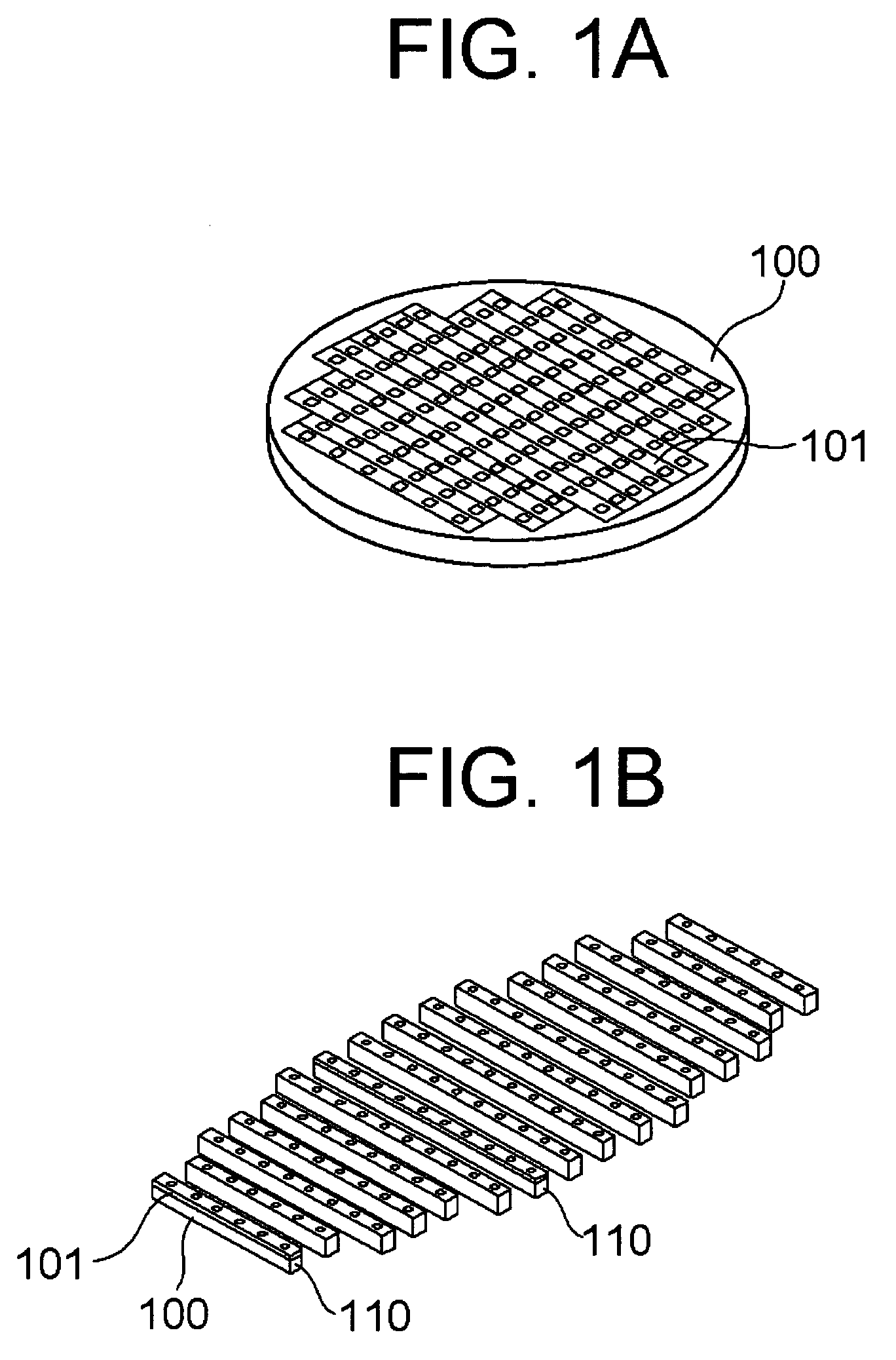
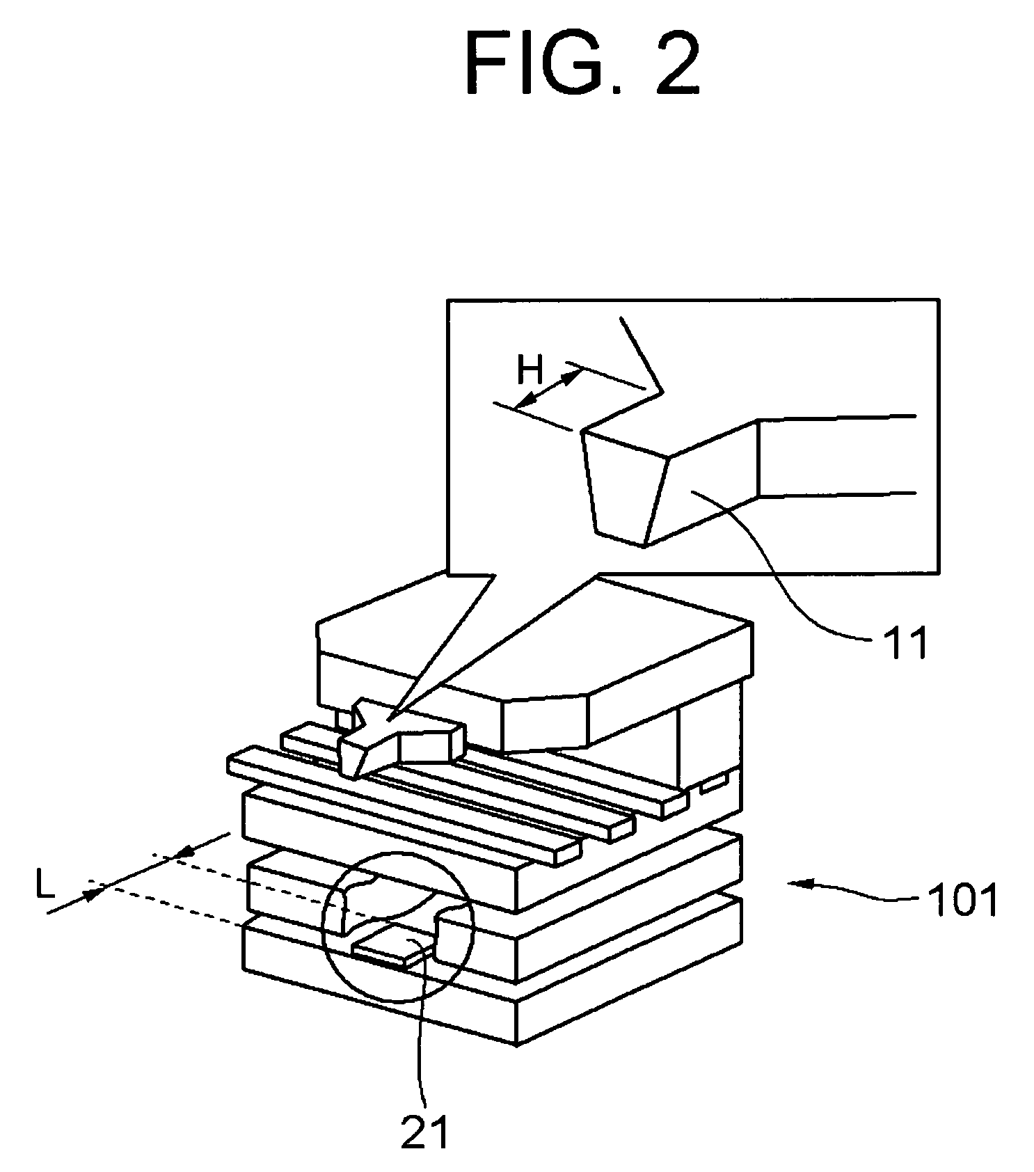
[0073]A first embodiment of the present invention will be described by referring to FIG. 1-FIG. 22. FIG. 1 is an illustration showing a state where magnetic heads are stacked on a substrate. FIG. 2 and FIG. 3 are illustrations showing the laminated structure of the magnetic head part. FIG. 4 and FIG. 5 are illustrations showing the structure of a reproducing-element forming layer and a recording-element forming layer. FIG. 6-FIG. 12 are illustrations showing the structure of the reproducing-element forming layer and the recording-element forming layer, and a state at the time of polishing. FIG. 13 is an illustration showing a state of measurements, when polishing a magnetic head slider. FIG. 14 shows illustrations of states at the time of adjusting polishing angle for the magnetic head slider. FIG. 15 is an illustration showing a state when cutting out magnetic head sliders from a bar block. FIG. 16 shows illustrations for describing a relation between the thickness of the sensor an...

second embodiment

[0105]Next, a second embodiment of the present invention will be described by referring to FIG. 23-FIG. 29. In this embodiment, basically, magnetic head sliders are manufactured by the magnetic head slider manufacturing method described above. However, the second embodiment further includes a step for adjusting the lengths of the recording element 11 and the reproducing element 21 with still higher precision. The step added to the first embodiment will be described in detail hereinafter.

[0106]First, in the stacked-layer forming step of the second embodiment, a pair of polishing-end detecting sensors having the same structure as the above-described recording-element polish amount detecting sensor 12 is formed on the same layer as that of the recording element 11 or on another layer. The recording-element polish amount detecting sensor 12 and the reproducing-element polish amount detecting sensor 22 may also be used as a pair of polishing-end detecting sensors. However, described in t...


PUM

PropertyMeasurementUnit
Lengthaaaaaaaaaa
Angleaaaaaaaaaa

Abstract

To provide a manufacturing method which can adjust the lengths of a recording element and a reproducing element for enabling manufacture of high-quality magnetic head sliders. The manufacturing method comprises: a stacked-layer forming step which stacks magnetic heads on a substrate; a lapping step which cuts out a bar block having a plurality of connected magnetic head sliders, and polishes a flying surface; and a slider cutting step which cuts out individual magnetic head sliders from the bar block. The stacked-layer forming step forms a reproducing-element polish amount detecting sensor on a same layer as that of the reproducing element, and forms a recording-element polish amount detecting sensor on a same layer as that of the recording element. The lapping step carries out polishing based on each output value of the reproducing-element polish amount detecting sensor and the recording-element polish amount detecting sensor.

Description

BACKGROUND OF THE INVENTION[0001]1. Field of the Invention[0002]The present invention relates to a magnetic head slider manufacturing method and, more specifically, to a method for manufacturing a magnetic head slider that has a magnetic head formed with thin films.[0003]2. Description of the Related Art[0004]Recent advancement in the recording density of magnetic disk devices has been remarkable, and it has continued to grow. So far, mainly employed is a recording method called a longitudinal recording method which places magnetic data horizontally with respect to a disk surface. With the longitudinal recording method, however, magnetic poles repel each other. Thus, it is difficult to have higher density. Even if it becomes possible to achieve higher density by suppressing repelling of the magnetic poles through thinning films of a recording medium, it is unavoidable to have an issue of heat disturbance with which the recording magnetization becomes unstable because of the heat ene...

Claims


Application Information

Patent Timeline
IPC IPC(8): G11B5/60B44C1/22C23F1/08
CPCG11B5/102G11B5/3166G11B5/3169G11B5/3173Y10T29/49048Y10T29/49039Y10T29/49044Y10T29/49046Y10T29/49052Y10T29/49043
Inventor FUJII, RYUJIONODERA, IKUHITOWANG, QUAN BAOKURIBAYASHI, MASAHIRO
Owner SAE MAGNETICS (HK) LTD
Why Eureka
Try Eureka